


Thanks to the development of single chip CMOS image sensors, low-cost image processors and miniaturized optics, many manufacturers have developed intelligent cameras in small footprint packages.
These devices have been widely embraced in a number of consumer applications such as mobile phones, notebook PCs and in automobile-based systems.
The manufacture of such miniature cameras, however, is not without its challenges. As sensors continue to increase in resolution and their pixel pitch becomes smaller, the spatial resolution of the image sensor must be matched to that of the lens. Even if that design consideration is taken into account, manufacturers must still inspect the camera to ensure that the lens is aligned correctly. In doing so, they can be assured that the CMOS sensor in the camera can capture an image that is both sharp and sports the contrast demanded by the system.
Compounding the inspection task is the fact that -- in today’s manufacturing environment -- the lenses in such miniature cameras are fixed into the body of the devices with adhesive, rather than on a traditional lens mount. Hence the alignment of the lenses inside the units must be tested during the manufacturing process to ensure that the lens is optimally situated within the unit.
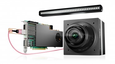
To enable manufacturers to build such camera modules in a production environment, engineers at Trioptics have developed a stand-alone system called the ProCam Align that can be used to manufacture multiple module types within one production line (Figure 1).

Figure 1: To enable manufacturers to build camera modules in a production environment, engineers at Trioptics have developed a stand-alone system called the ProCam Align that can be used to manufacture multiple module types within one production line.
The system automatically dispenses glue onto the body of the camera, after which it assembles the lens onto it. It then aligns the lens inside the unit, and once this has been achieved, the system cures the adhesive, locking the lens into place.
The effects of misalignment
According to Dr. Daniel Winters, a research and development manager at Trioptics, the effects of lens misalignment can be highly pronounced. If, for example, the lens is shifted in the x, y plane from its optimum position, the image captured by the sensor will also be shifted by a corresponding amount. If the lens is not mounted correctly in the z plane, then the result will be an image that is not perfectly focused. If the lens is tilted, part of the image captured by the sensor may be in focus while another part of the image will be blurred.
To correct for such deviations during the manufacturing process, an operator first places the body of the camera with the CMOS imager and the lens to be affixed to it into two housings within the ProCam unit. The CMOS imager is then connected to a PC-based system inside the unit via a cable. To accommodate a number of different camera types, a variety of interfaces are supported by the system including the popular USB, GigE, Firewire and Cameralink interfaces.
Under the control of a PC inside the system, a linear guide moves the lens and the imager inside the unit where adhesive is applied to the inner rim of the body of the housing of the imager by a robotic dispensing arm (Figure 2). Having done so, an electric actuator then moves both the imager and the lens to an assembly station inside the unit. Here, two grippers attached to a hexapod robot with six degrees of freedom lifts the lens from its housing and places it directly into the body of the unit.

Figure 2: Under the control of a system PC, the lens and the imager are moved inside the unit where adhesive is automatically applied to the inner rim of the housing of the imager using a robotic dispensing arm.
To determine the precise position that the lens should be finally fixed inside the camera assembly, a test pattern is projected onto the camera assembly from a target generator situated above the camera. The test pattern comprises a series of cross hairs that are projected across the imager in the camera. Once the test image has been captured by the sensor, the resultant image is then transferred to the system PC for analysis.
From the image of the test pattern, the system software creates Modulation Transfer Function (MTF) curves for each of the points on the image. The modulation functions are plotted with the contrast value -- or sharpness of the cross hairs -- vertically, in percent, while the distance the individual cross hairs are away from the center of the image are plotted horizontally.
The system software then analyzes the MTF curves of each of the cross hairs in the image and determines the optimum alignment of the lens and sensor in six dimensions (x/y/z, tilt and rotation) so that all points on the image are focused as precisely as possible (Figure 3).

Figure 3: System software analyzes MTF curves to determine the sharpness of the image. Having done so, the software instructs the hexapod robot to move grippers holding the lens in the z plane to ensure that all the points on the image are focused as precisely as possible.
These results are then passed to the hexapod robot which uses the grippers to tilt, shift and rotate the lens to its optimal position in the unit.
Fixing the lens into the assembly
Having optimized the position of the lens within the camera unit, lamps placed around the camera apply UV light to cure the adhesive and fix the lens into the assembly. Once the adhesive has been set, a linear guide then moves the camera to a station where an operator can remove the unit from the system and place a new one into it.
Of course, not all camera modules are created with the same purpose in mind. In some cases, for example, they may be specifically designed to image targets at infinite distances from the imager. In other applications, they may be designed to capture wide angle fields of view.
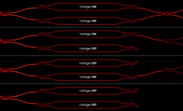
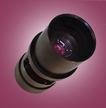
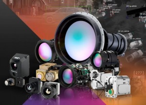
To accommodate these different types of modules, a camera must be presented with test patterns that are representative of the environment that the camera will eventually be used in. To do so, the projection unit in the ProCam unit can be fitted with a set of collimating lenses. Attached onto a set of linear guides, the motorized lenses can be moved under PC control to replicate a target at variable distance up to infinity without parallax. To adjust for different fields of view of the camera module (Figure 4 at top), the angles under which the target patterns are projected can be changed as well.
Naturally enough, most manufacturers of such cameras are concerned with the degree of accuracy with which the system can perform alignment of the lens within the camera. According to Dr. Winters, the sensor can be aligned with the camera optics with sub-micron and sub-arcmin resolution. More specifically, the ProCam align system can provide a linear resolution of 0.2um and a linear accuracy of less than 2um. In terms of rotation, the unit offers a rotation resolution of 1.8 arcseconds and a rotation accuracy of 20arcseconds. Tilt alignment accuracy of the system is specified as 2 arcminutes.
Through the use of such active alignment systems, manufacturers can be assured of the image quality of their products, while decreasing the number of rejects. What is more, the measurement data that is captured during the manufacturing process can be stored or written to a database to enable manufacturers to perform traceability analyses on their product lines.
Written by Dave Wilson, Senior Editor, Novus Light Technologies Today
Photo at top: Attached onto a set of linear guides, motorized collimating lenses can be moved under PC control to replicate a target at infinity without parallax, and to control the field of view of the image that is projected onto the imager.