


To support more sophisticated and compact tablets, phones, watches and other wearables, the shrinking of semiconductor dies and packaged devices is proving as critical to microelectronics development as the relentless miniaturization defined by Moore’s Law. This advanced packaging trend creates numerous opportunities for lasers because of their unique ability to perform diverse materials processing tasks with high precision and minimal heat affected zone (HAZ). As a result, laser use is increasing in wafer dicing, package singulation, optical debonding, µ-via drilling, RDL (redistribution layer) structuring, dicing tape cutting (EMI shield), soldering, annealing and bonding, to name just a few. In this article, we review three quite different laser-based processes for this very dynamic applications area.
SiP singulation with nanosecond and picosecond lasers
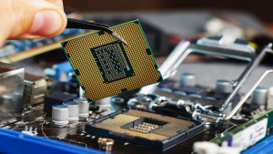
System-In-Package (SiP) technology provides a high degree of functionality in a very small volume for high-end wearables or portable devices. SiP devices consist of circuit components, such as a processor, memory, communication chip & sensors, on a PCB substrate which contains embedded copper traces. The entire assembly is typically encapsulated in molding compound, and an outer conductive coating for electromagnetic shielding may be added. The entire SiP device is usually around 1 mm thick, and the mold compound typically accounts for about half this total.
During fabrication, multiple SiP devices are made on a large panel and eventually singulated to individual devices. Furthermore, in some cases, trenches are cut into the molding compound in individual devices all the way down to a copper ground plane. This is done before coating the device with a conductive shield which serves to completely surround a subregion of the SiP and shield it from other high frequency subcomponents.
For both singulation and trenching, the cuts have to be precise in both location and depth, without charring, and free of debris. Additionally, cutting process effects such as heat damage, delamination, or micro-cracks pose unacceptable failure risks for these circuits.
Currently, 20-40 W, UV solid-state lasers with nanosecond pulsewidths (e.g., Coherent AVIA) are the primary tools for SiP cutting. However, with nanosecond sources there is a tradeoff between output power and cut quality – specifically edge quality and debris formation. Thus, process speed cannot be easily increased simply by applying more laser power.
As a result, 532 nm (green) ultra-short pulse (USP) lasers such as the Coherent HyperRapid NX picosecond laser and Monaco femtosecond laser can be an alternative when the cut quality is of utmost importance. These produce a smaller kerf, reduced HAZ, and less debris as compared to nanosecond lasers, and can under certain circumstances also lead to higher throughput. The disadvantage of USP sources is their higher capital cost.


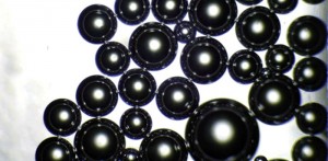
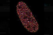
Figure 1: Cross section of a 1.2 mm thick SiP material cut with a picosecond (top) vs. nanosecond (bottom).
Redistribution layer structuring with excimer lasers
Redistribution layers (RDLs) are key to the implementation of virtually all types of advanced packages in microelectronics, including flip chip, wafer-level chip scale packages, fan out wafer-level packaging, embedded IC, and 2.5D/3D packages. RDLs are routing circuitry created by patterning metal and dielectric layers that allows each silicon die to be connected to other dies. In this way RDLs serve to re-route the input/output of a die.
Currently, many RDLs are structured using “photodefinable” dielectrics where the desired circuit pattern is printed by photolithography and then wet developed to remove either the exposed or unexposed areas. But photodefinable polymers have several drawbacks, including high cost, complex processing and poor matching of coefficient of thermal expansion (CTE) with the material to which they are to be bonded. In addition there is a risk of losing a good die due to circuit failures from resist remnants.
A newer solution is to use a suitable non-photo dielectric material and incorporate direct ablative patterning with a 308 nm excimer laser. These non-photo dielectrics are substantially less costly than the photodefinable materials, and also produce less stress, better CTE matching, and have vastly improved mechanical and electrical properties. Here, the laser is projected through a mask containing the desired pattern to be produced, and the substrate (which is larger than the projected pattern) is ablated, moved, and then ablated again, until all the desired areas have been patterned. Excimer laser ablation is a cost-effective, high-throughput patterning method because it involves fewer steps than photodefinable dielectric patterning and eliminates wet chemicals for a “greener” process.
Excimer laser based tools for RDL structuring are already in use based on the Coherent LAMBDA SX series excimers. The high pulse energy (>1 J) and repetition rate (300 Hz) of these excimer lasers provide rapid throughput for feature sizes down to 2 µm. In addition, excimer laser ablation demonstrates excellent control of feature depth and “wall angle.” The latter is important because subsequent metal sputtering or vapor deposition processes can be degraded by “shadowing” on the sides of steep angled features.

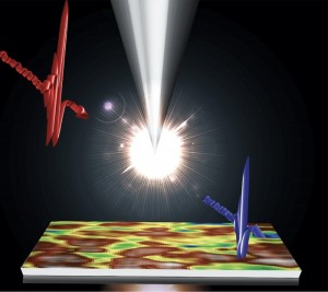
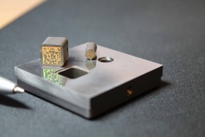
Figure 2: Excimer laser ablation produces clean, small features in polyimide. Courtesy of SÜSS Microtec.
LTCC scribing and srilling with CO2 and CO lasers
Other important packaging applications involve low temperature co-fired ceramics (LTCC) which are increasingly popular as microelectronics substrates for power or communication devices. LTCCs are processed as a layer of green (unfired) ceramic, typically in the 50 µm to 250 μm range, fabricated on a polyethylene trichloride (PET) tape layer of about 40 µm to 60 μm thickness. Lasers are utilized for two key tasks in LTCC circuit fabrication: scribing (singulation) and via drilling.
Historically, CO2 lasers have been employed for LTCC scribing. Here the laser is used to create a line of closely spaced holes penetrating partway into the substrate (i.e. scribes). Mechanical force is then used to snap the material along this scribe line.
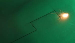
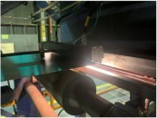
Today, the CO laser is attracting increased interest as an alternative in this application. Industrial CO lasers, which were introduced to the market a few years ago by Coherent, are similar to CO2 technology, except that they output at a wavelength of ~5 µm. Absorption of this shorter wavelength in LTCC is significantly lower than at the CO2 wavelength of 10.6 µm. This allows the laser to penetrate farther into the substrate, creating a deeper scribe, which is then easier to break – see figure 3. The lower absorption also creates a smaller HAZ.
LTCC via drilling also has traditionally relied on the CO2 laser. But for this application, green wavelength USP lasers may ultimately emerge as the preferred alternative, rather than CO2. This is because USP lasers offer the best balance between quality and throughput speed. Specifically, a 50 W green USP laser can produce 30 µm vias at a rate of over 2000 holes/second in 0.60 mm ceramic. However, CO lasers could offer an alternative to USP lasers. CO lasers have demonstrated drilling ~40 µm vias in 0.65mm thick fired ceramic at ~1000 holes/second. So depending on the thickness of the ceramic and the desired diameter, both USP and CO lasers are excellent choices for via drilling in LTCC.

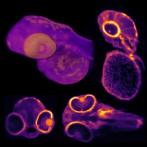
Figure 3: Cross section of 0.6mm thick scribed LTCC. The comparison shows the CO laser’s scribe penetrating further and generating higher aspect ratio holes due to its lower absorption in the ceramic. The CO2 process also shows more charring at the entrance and larger diameter holes.
Similar, fundamental benefits
In conclusion, while semiconductor packaging currently uses a diverse range of laser technologies, they all offer similar fundamental benefits. Specifically, these include non-contact processing that produces highly precise features, usually with minimal effect on surrounding material, and often at high throughput. Plus, laser processing is “green” in that it frequently eliminates the need to use chemicals that are hazardous to use or difficult to dispose.
By Dirk Müller, Rainer Pätzel, George Oulundsen, Hatim Haloui and Ed Rea, Coherent Inc.