


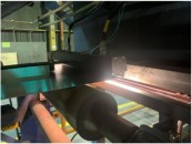


Monitoring oil and gas wells requires use of state-of-the-art sensing technologies in order to increase production while doing the least harm to the environment surrounding the well. Around 20 years ago the oil and gas industry began using single-point fibre-optic sensors and distributed fibre-optic sensing. Today’s state-of-the-art method is a fibre-optic sensing concept known as distributed acoustic sensing (DAS), and not surprisingly, it has attracted a great deal of interest in oil and gas applications.
Advantages to DAS
DAS brings a capability that has been unobtainable to date, which is the ability to monitor (detect) acoustic events continuously throughout the entire length of the fibre. Compared to monitoring with distributed temperature sensing, it offers the ability to see what goes on where one cannot see, and it does so with previously unobtainable levels of reliability, precision and granularity. Jeff Bush, President of Optiphase, an OEM manufacturer of electronic equipment including DAS technology, pointed out that DAS does not replace DTS. DAS is a dynamic sensor, while DTS is static, and the two can work hand in hand.
How DAS works
The DAS concept (originally conceived for physical security applications) is based on a phenomenon called Rayleigh scattering, named after the British physicist Lord Rayleigh (John William Strut, 1842-1919) who initially discovered the phenomenon. The basis of this technology is based on optical time domain reflectometry (OTDR). An optical pulse is launched into the fibre and minute portions of the light traveling outward are (Rayleigh) scattered backwards in a distributed manner such that this scattered light returning may be measured temporally with a fast receiver to produce a record or trace of distributed loss of the fibre out to distances of 10’s of Km.
DAS has the ability of monitoring (detecting) acoustic events continuously throughout the entire length of the fibre.
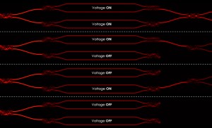
If the optical pulses are made with a narrow line width, high coherence laser , then these scattered return light signals will interfere with each other causing signal ripples that superimpose the loss trace. This is shown in Figure 1. These ripples, because they are related to the fixed Rayleigh scatter sites within a fibre, are static as long as the fibre is static. If the fibre experiences any perturbations, or external forces, which strain the fibre, the positions of the scatter sites change. This in turn changes the interferometric induced ripples.
Dynamic sensitivities down to the few angstrom levels are achievable. The result is a highly sensitive distributed sensing mechanism, known as Coherent Optical Time Domain Reflectometry (COTDR), and more recently known as Distributed Acoustic Sensing (DAS).

Figure 1. OTDR configuration shows pulsed light injected into distributed fibre sensor. The resulting trace resulting from the Rayleigh backscatter in the fibre is shown as the black curve. If the laser is highly coherent, the trace develops “ripples” (red curve) resulting from interference of the scattered light.
Typical pulse widths used with current day systems range from 10 to a few hundred nano-seconds. If one considers a 100ns pulse, sensing resolution within a fiber becomes 10 meters. Thus a 10 km long fibre is enabled to represent 1000 separate sensor zones. The advantage is that this can be done for the price of a single-mode fibre.
Oil & gas applications
The proposition of a low-cost, thermally robust (up to 300°C) distributed fiber sensor for dynamic measurements opens the door to a wide range of potential applications for down-hole and other oil and gas related sensing. The short list includes;
- Vertical seismic profiling
- DAS adds acoustic component to 3C seismic to comprise 4C measurement
- DAS as stand-alone for velocity measurements and tube wave detection
- Hydraulic fracture stimulation diagnostics (cross-well, in-well)
- Wireline distributed acoustic sensing (various apps)
- Real-time casing imager (RCTI) for real-time completion monitoring (RTCM)
- Monitoring of permanent casing installations (tandem with DTS)
- Carbon dioxide sequestration monitoring (in-well)
- Pipeline condition monitoring (structure health, leak detection, intrusion detection)
- Other asset monitoring (structural health and security)
A few of the companies with DAS solutions include Fotech Solutions, Silixa and Optasense.
An example of how DAS is applied in the oil and gas industry can be seen in the use of Silixa's intelligent Distributed Acoustic Sensor called iDAS. It is a system that can work in tandem with a DTS system, and can record the true acoustic signal in real time along tens of kilometres of standard optical fibres. Silixa says that iDAS offers precise amplitude and phase measurements with a wide dynamic range (>120dB) and no cross-talk. The system is currently being used by Chevron in the field. Applications include seismic appraisal at the borehole, cement evaluation, monitoring fracturing and fracture analysis, flow profiling, monitoring casing leaks, gas lift and electric submersible pump optimization. The company has developed a range of embedded data handling and visualization tools that help process the data generated by both the DAS and DTS systems. Jeff Bush of Optiphase said “to enable the technology to be useful it’s got to be handled in real time.” He explained that the signal processing requirements are substantial. “Users have a data pipe with as much as 10Gbit/s of information coming back. If you don’t process that in real time, there’s no way you’re going to keep up with it.”
The acoustic picture DAS provides enables operators to be better able to have a good view of what is happening and to react to it instantly.
OptaSense has developed a system in collaboration with Shell Oil specifically for use in the oil and gas field to monitor the fracking process. According to Barry Lycett, Head of Marketing for OptaSense, in oil fields the system is helping to improve process because it can monitor and relay information in real time. “It’s a better process because they don’t have to stop oil production.” This increases yield as well as offering environmental benefits because the acoustic picture DAS provides enables operators to be better able to have a good view of what is happening and to react to it instantly, if necessary.
Two types of DAS
Time domain DAS interrogation as practiced today takes on two distinct forms. The first and earliest practiced form is optical intensity based (DASI). The second form, which is based on more recent developments, is optical phase-based (DASP). DASI involves measuring the “trace” of the intensity signals resulting from pulse backscatter terms that self-interfere. This simple approach yields a non-linear and compressed measure of the acoustic signal. Despite signal infirmities, DASI is still quite effective when used for applications such as intrusion detection. However, it isn’t particularly effective when signal processing techniques require coherent array processing methods.
DASP interrogation is focused on avoiding the DASI type errors and implement interferometric interrogation approaches, which enable optical phase demodulation to extract a precise measure of the acoustic signal. These approaches are intended to provide for stable and linear representations of the distributed acoustic signals and are highly suited for coherent array processing such as that commonly used for conventional geophones, accelerometer and hydrophone sensor arrays.
An example of the differences between the two interrogation techniques is shown in Figure 2.
 replicates the waveform of the acoustic signal. The DASI interrogation method, being substantially non-linear presents as that shown on the bottom curve.")
Figure 2: The linear representation (DASP) replicates the waveform of the acoustic signal. The DASI interrogation method, being substantially non-linear presents as that shown on the bottom curve.
Current DAS systems for oil and gas applications use both DASI and DASP interrogation with DASI representing the vast majority of offerings. As the market progresses, it is not unreasonable to expect that product offerings will migrate to DASP as users provide more of the input to their requirements.
Written by Anne Fischer, Managing Editor, Novus Light Technologies Today