


Many contemporary industrial vision systems rely on cable/connector assemblies to link cameras to computers. Despite that fact, few systems integrators would claim that specifying such an assembly is a top priority when configuring their systems. With the advent of higher speed interconnection schemes such as CoaXPress, however, doing so has never been more important.
According to Rick Ragnini, Product Developer at Components Express, the fact that the latest version of CoaXPress (CXP) is now capable of delivering 12.5GBit/sec of data over co-axial cable has presented new challenges to both cable manufacturers and systems integrators who may wish to implement faster systems, or upgrade slower speed systems that are currently deployed in the field.
The co-axial cable used in all CoaXPress systems has a central core shielded by a dielectric insulator wrapped in a conducting metal shield and contained in a plastic jacket. Although co-axial cables can be supplied with a range of impedances, typically 50, 75 and 93 ohm, CoaXPress specifies that the cable impedance should be 75 ohm, a cable that provides an adequate means of maintaining signal strength.
As the speed at which bits can be transmitted down a CoaXPress cable is increased, so too is the frequency of the signal transmitted down the cable. At CXP-6 speeds of 6.25Gbit/sec, the frequency of the signal transmitted is 3.125GHz. At CXP-12 speeds of 12.5Gbit/sec, the frequency is 6.25GHz.
Although the signal loss (or attenuation) of the co-axial cable depends on its length, it is also dependent on the frequency of the system. However, the attenuation is not linearly dependent on frequency, since the loss is due to a combination of resistive, dielectric and radiated losses. As a result, system integrators will note that speed and length do not follow a linear relationship: a doubling of the speed of the CoaXPress interface does not necessarily mean that the length of the cable that can be used will need to be halved. Hence it is important that system integrators take advice from cable assembly suppliers who can provide comprehensive data about the optimal length of the cable that can be used in a specific CoaXPress system at a given speed.
Traditionally, of course, co-axial cable was used to facilitate the transmission of analog signals. And the effectiveness of the cable to transmit such signals was tested using analog means. Now that such cable has been repurposed to transmit digital signals, however, new means of testing the effectiveness of the cable must be employed.
Digital design
One of the important ways of characterizing co-axial cable is to perform a Bit Error Rate Test (BERT). In digital transmission systems such as CoaXPress, the number of bit errors is the number of received bits of a data stream that have been modified due to errors being introduced into the system by noise, interference or distortion. The bit error rate, on the other hand, is defined as the number of bit errors divided by the total number of transferred bits during a specific time interval. According to Euresys, it is generally accepted that a CoaXPress Link will operate reliably if the probability of a single bit error is less than 10-12.
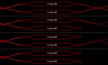
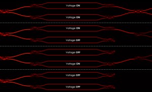
Fortunately, the CoaXPress protocol defines a bi-directional link test facility to test the quality of the link. Two link tests are defined: host-to-camera and camera-to-host. All link tests are initiated by the host. A pair of test pattern generators and receivers is included in both the host and the camera. The test generator transmits a link test packet containing a known test pattern. The test receiver compares the received test data packet against its local test generator. Test pass/fail statistics are accumulated and made available to the host.
For Components Express’ Ragnini and others involved in characterizing CoaXPress systems, tools such as Euresys CoaXPress Link Validation Tool (CXLVT) enable them to validate the operational parameters of a CoaXPress Link in terms of the bit rate, cable type, and cable length. The tool can be run until the user is 100% confident that the probability of a single bit error is within acceptable limits. In operation, the tool computes the confidence level, or likelihood, that the probability of single bit error is less than a value (such as 10-12) based on the measurement of the bit error rate during a sufficiently long time. When started, the CXLVT software displays these confidence levels, as evidence accumulates over time.
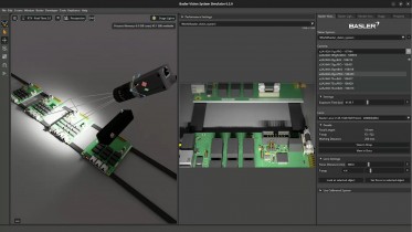
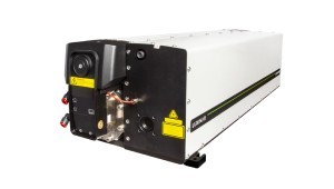
Aside from testing the BER of the cable, Ragnini says that it important to ensure that the entire cable assembly -- including the connectors and the cable they are attached to -- meet the cable requirements of the CoaXPress standard. To do this, the testing team at Components Express has invested in a Keysight Technologies Vector Network Analyzer (VNA) that has enabled engineers there to investigate, characterize, and troubleshoot these characteristics prior to shipment.

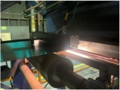
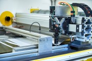
Keysight’s Vector Network Analyzer (VNA) enables engineers to investigate, characterize, and troubleshoot cable subassemblies prior to shipment.
In use, the test equipment uses a technique called time-domain reflectometry to characterize and locate any faults in the coaxial cable. To do so, the Keysight VNA measures reflections along the cable itself by transmitting a signal onto the conductor and measuring reflections due to mismatched impedances. A key measurement here is the Voltage Standing Wave Ratio (VSWR) which is a measure of how well the device transmitting a signal is matched to the device that is receiving it. Ideally, of course, both should be perfectly matched, but if they are not matched, power is reflected which causes a reflected voltage wave along the cable which can then be measured.
The Keysight VNA is capable of measuring the “return loss” which is the loss of power in the signal returned by any discontinuity in the cable. This can be caused by impedance mismatch with the terminating load or with a device inserted in the cable. While different systems have different acceptable return loss limits, -15 dB or better is a common system limit for a cable system and that is the limit chosen for CoaXPress. For CoaXPress systems running at 12.5Gbit/sec, the return loss for the cable must be tested at 6.25GHz.
One of the features of the CoaXPress interface is that each connection of the CoaXPress host connector is capable of delivering 1A of power per cable to the camera. To ensure that each cable subassembly is capable meeting this specification, Components Express also conducts insertion loss and resistance testing. Having said that, the factor limiting the length of the cable that can be used is the speed at which data is transmitted and this is the most important characteristic to be characterized.

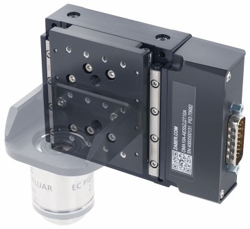
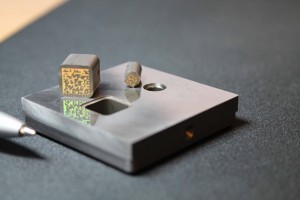
The Micro-BNC connector used with CXP-12 cables is smaller than standard BNC connectors while providing a robust mechanical connection with excellent signal properties.
Another factor to consider when implementing CXP-12 cabling is the use of Micro-BNC (also known as HD-BNC) connectors on new CXP-12 machine vision products. The Micro-BNC connector design is smaller than standard BNC connectors while providing a robust mechanical connection with excellent signal properties. It is important to note that cables using DIN 1.0/2.3 connectors should only be used at speeds up to an including CXP-6.
System implications
While Ragnini would not expect many systems integrators to become expert in the field of cable testing, he does warn that they should be aware of the implications of running systems at higher speeds, especially if they are considering migrating from an existing CXP-6 system to CXP-12. A systems integrator who wishes to upgrade a CXP-6 system to a CXP-12 system with new frame grabbers and cameras should be aware of the potential need to upgrade the cable too since a lot of existing cables are not rated for these higher speeds and frequency. And this, Ragnini says, could add additional costs to the system.
By performing a number of tests on their CoaXPress subassemblies, Ragnini says that Components Express has come up with some figures for cable length at which a 12.5GBit/sec CXP-12 system can be safely operated without incurring any errors. Having done so, he would recommend a maximum cable length of around 40m for a fast 12.5Gbit/sec CXP-12 system. However, due to the fact that cable length cannot be directly correlated to speed, he acknowledges that the most propitious way to specify cable for a system is thorough assembly testing for each individual application.
Compounding the challenges involved in the cable length specification process is the fact that two vendors -- Microchip Technology and Macom -- now supply Physical Interface Devices (PYD) for the CoaXPress interface, and hence developers of frame grabbers will be supplying interface boards based on both devices. According to Ragnini, this means that Components Express, for one, will now be rating the length of the cable subassemblies that it provides to systems integrators according to which physical layer interface device is used in their customers’ systems.
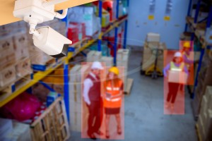
Lastly, Ragnini advises that systems integrators consider the environment that the CoaXPress system is likely to be used in. If the CoaXPress system is destined for use in a robotics application, C-track testing will be required to flex or twist the cables to determine how they degrade over time and enable a cable/assembly supplier to assign a lifetime rating on them. Ragnini says that where the twisting of a cable is a real issue for a systems integrator, rotary couplings can be employed along the cable to alleviate the issue.
Written by Dave Wilson, Senior Editor, Novus Light Technologies Today