


As Moore’s Law is progressively more difficult and expensive to sustain, the microelectronics industry must develop disruptive ways to increase device performances. 3D technology consisting in stacking two devices vertically is a very promising path and has reached mass production maturity in specific applications like backside illuminated imagers [1]. Different integration processes could be used to stack devices. The electrical interconnections could be added after stacking and thinning the top device [2], but embedding them directly at the bonding interface is the ideal solution for 3D interconnection. This could be achieved with indium balls, CuSnAg bumps or copper pillars, but high density of interconnections is not possible, and the throughput of these bonding solutions is limited. Reaching interconnection density above 108/cm², for instance, and processing more than 20 bonded pairs per hour with one bonding tool, requires direct-bonding technology.
Direct bonding interests and challenges
In the early 2000s, Shigetou et al. [3] proposed direct bonding with embedded interconnections, which has several intrinsic advantages. The bonding technique is performed at room temperature and ambient pressure, and spontaneous bonding is achieved between the two prepared surfaces without using any polymer or other bonded materials between them. Obviously, to have electrical interconnections directly at the bonding interface, precise alignment of the two wafers is essential during bonding. Performing the bonding at room temperature makes it easier to reach the alignment accuracy, which should be far below 1µm, in order to reach the high-density interconnection specification mentioned above. Moreover, the adhesion energy of standard hydrophilic copper or silicon-oxide direct bonding is between 50 mJ/m² and 100 mJ/m². This allows a self-propagation of the bonding on standard microelectronic 200mm or 300mm wafers with a bonding wave speed around 20 mm/s, which supports fairly high throughput. However, the main drawback of direct bonding is its demanding surface specification: bonding yield decreases rapidly if cleanliness, roughness and topography are not controlled very tightly. A particle of 1µm height can induce a bonding defect of several cm².
Hybrid copper/oxide bonding specifications
Moreover, in order to have interconnections at the bonding interface, isolated metallic pads must be prepared with their top surface exactly at the same bonded plane. The isolation can be done with an air or vacuum gap, but the use of an insulating material is preferred to enhance the mechanical stability of the bonded interface, as well as the bonding area. The damascene process used in the back-end process of almost all microelectronic chips allows hybrid surfaces such as copper/oxide to be obtained with very good planarity. The hydrophilic bonding mechanisms of both SiO2/SiO2 and Cu/Cu are compatible [4-6], and after exposure to post-bonding annealing temperatures of only 300°C, both bonding types reach relatively high bonding energies (>4 J/m²). This makes hybrid copper/oxide bonding a promising technology for microelectronic 3D integration.
Hybrid surfaces compatible with direct bonding can be prepared with bonding propagation on both oxide and copper areas, obviously after fine tuning the CMP (chemical mechanical polishing) damascene process with an adapted copper pad design. As noted, adding reliable electrical interconnections requires aligning the wafers before the bonding, and the alignment accuracy must be significantly smaller than the copper pad dimension and spacing. The sum of these two dimensions is called the pitch. Assuming a square copper pad with width equal to half of the pitch, a 1µm pitch hydride surface will be comprised of 500nm copper pad separated by 500nm of silicon oxide. If a factor of four is taken between the pitch and the alignment specification, the alignment accuracy should then be 250nm at any point of the entire hybrid surface. If enough alignment marks are embedded at the bonding interface, the 3s alignment statistic of all these marks should be below 200nm with a distribution well centered at +-50nm. It requires a specific direct bonding tool to achieve such high alignment accuracy.
Aligning and direct bonding the wafers
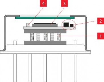
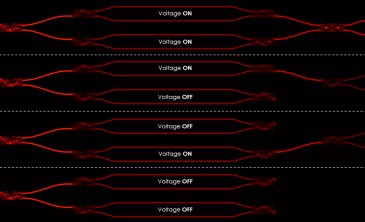
At Leti, we used an EVG Gemini FB bonding tool, which contains a SmartView NT2 system and an Alignment Verification Module (AVM), in addition to the standard direct bonding cleaning and plasma stations. The SmartView system performs the alignment and the direct bonding at the same time, currently using two diametrically opposed marks on each wafer for the alignment. For the alignment process shown in Figure 1, topside microscopes are used to detect the alignment mark positions on the bottom wafer (the top wafer stage is retracted), which are recorded in the software. Next, the bottom-side stage is retracted to allow the bottom-side microscopes to detect the alignment marks on the top wafer.

Figure 1: SmartView patented alignment used for high-precision wafer bonding
The software is then used to calculate the perfect overlay position for the two wafers. Adjusting the stage positions according to the positions calculated by the software aligns the wafers. During all of these alignment process steps, the wafers are parallel and separated by less than 75µm, which allows the direct bonding wave to be started with only a small top and/or bottom deformation. This maintains a good alignment of the bonding process.
After the bonding, if enough alignment marks are embedded at the bonding interface, the AVM module is able to measure the alignment statistic as shown in Figure 2.
 ± (194 nm / 162 nm) 3ï³ in x/y direction.")
Figure 2: AVM measurement of SmartView bonded wafers. Alignment is (-14 nm / -15 nm) ± (194 nm / 162 nm) 3s in x/y direction.
These results can then be used to include offsets in the next alignment process to enhance the alignment performance and to overcome any tool drift. An advantage of direct bonding over other bonding technologies is that if the bonding alignment is not perfect, the wafers can be debonded and reworked.
Leti’s hybrid wafer bonding technology allows repeated alignment of two surfaces of 110 square inches each with a precision 500 times smaller than the width of a human hair. With this process and EVG’s Gemini FB bonding tool, Leti demonstrated an alignment precision of 200 nm (3s) for 300 mm diameter wafers with a hybrid pitch below 1 µm. It is the finest pitch bonded up to now.
Written by Frank Fournel PhD, CEA International Expert, Engineering Bonding Team Manager
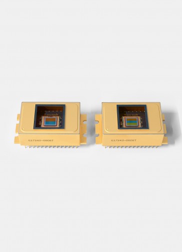
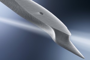
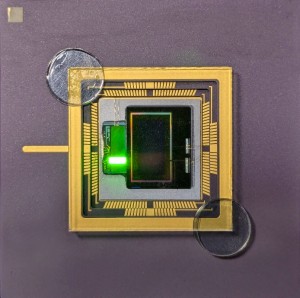
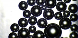
Image at top: Scanning electron microscopy (SEM) images (3D view) of the 3D assembly including all metal levels of the BSI imager structure
References:
1Y. Kagawa, N. Fujii, K. Aoyagi, Y. Kobayashi, S. Nishi, S. Takeshita, J. Taura, H. Takahashi, Y. Nishimura, and K. Tatani, IISS R01 (2017).
2http://techon.nikkeibp.co.jp/english/NEWS_EN/20130222/267487/
3A. Shigetou, N. Hosoda, T. Itoh, and T. Suga, in 2001 Proceedings. 51st Electronic Components and Technology Conference (Cat. No.01CH37220) (2001), pp. 755–760.
4F. Fournel, C. Martin-Cocher, D. Radisson, V. Larrey, E. Beche, C. Morales, P.A. Delean, F. Rieutord, and H. Moriceau, ECS J. Solid State Sci. Technol. 4, P124 (2015).
5F. Fournel, M. Tedjini, V. Larrey, F. Rieutord, C. Morales, C. Bridoux, and H. Moriceau, ECS Trans. 75, 129 (2016).
6P. Gondcharton, B. Imbert, L. Benaissa, V. Carron, and M. Verdier, Microsystem Technologies 21, 995 (2015).