


In many industrial applications where visual inspection can be challenging due to low contrast or highly reflective imaging conditions, polarized sensors can help to uncover hidden material properties and provide visual clarity over standard cameras.
Polarization cameras, for example, can be used to inspect transparent materials such as glass or plastic. Using a false color image to visualize the polarized angle of the image can help identify scratches on surfaces of clear plastics. The same method can be used to look at bi-refringent material to evaluate internal stress. Polarized image data can also produce high contrast images that can be used for object identification and segmentation. Surfaces that are strongly polarized can create high contrast images if captured with a polarization camera.
According to LUCID Vision Labs, polarization also brings many advantages for other industries such as chemical, pharmaceutical, food and beverage. Many chemical compounds, such as active pharmaceutical ingredients or sugar, are “optically active” and cause a change in the polarization of light. The amount of change is determined by the nature and the concentration of the compound, allowing the use of polarimetry to detect and quantify these compounds.
Polarizing cameras
In the past, one way that manufacturers built polarization cameras was to mount a rotating mechanical polarizing filter wheel above the sensor in the camera. More recently, in an attempt to reduce the cost and complexity of such systems, some manufacturers mounted area-dividing, sub-wavelength structure (SWS) polarization filters on glass directly above their CMOS sensors to enable their cameras to acquire polarization information in real-time.
Recently, however, with the advent of the Sony IMX250MZR CMOS 5.0 MPixel sensor, camera makers now have a ready made solution. Rather than develop and mount a custom built polarizer above an existing imager, they can now employ the new Sony sensor which itself incorporates a layer of polarizing filters above the photodiodes in the imager. This increases the speed of a vision system compared to earlier mechanical designs by increasing the throughput of the system.
The Sony global shutter IMX250MZR CMOS sensor maintains the same pixel size, frame rate and optical format as the popular IMX250 it is based on. With 2064 x 2056 (5MPixels), a 2/3" optical format, and a pixel size of 3.45 microns, the sensor sports a frame rate of 97 frames/sec (in 8 bit mode), 79 frames/sec (in 10 bit mode), and 35 frames/sec (in 12 bit mode). While the addition of the polarizer may lower the quantum efficiency of the device, the IMX250MZR shares the low read noise characteristic of other Sony Pregius sensors.
Lucid Vision Labs is already shipping cameras, while products from FLIR, JAI, Imperx, Sony and Teledyne Dalsa's cameras will be shipping this year. Other leading camera manufacturers such as Basler and IDS Imaging Solutions are known to be evaluating the abilities of the new Sony sensor in their research and development facilities.
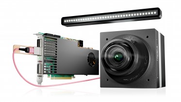
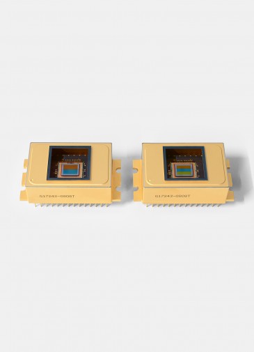
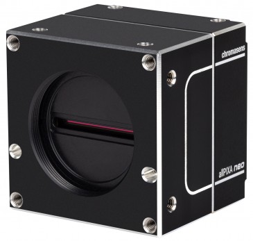
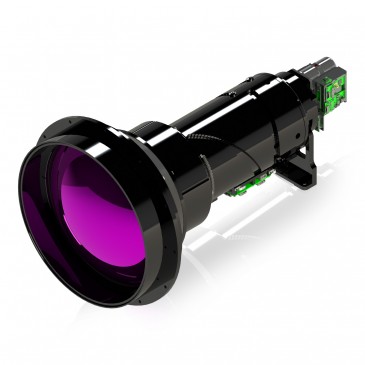
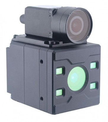
Manufacturers have chosen to build cameras with different interfaces to meet the needs of the vision market (Figure 1).


Figure 1: Five new polarization cameras all use the new Sony IMX250MZR CMOS 5.0 MPixel sensor. (Top) Lucid’s new Phoenix GigE PoE camera is a micro compact camera with a versatile board design, measuring only 24 x 24 mm. (Second Image) Imperx’ Cheetah C2420Z camera currently supports the Camera Link interface, but a USB3 version is expected soon. (Third Image) JAI’s GO-5100MP-USB is equipped with a USB3 Vision interface. (Forth Image) FLIR’s BFS-U3-51S5P-C offering is based on the USB 3.1 Gen 1 interface. (Fifth image). Teledyne DALSA’s Genie Nano-M2450-Polarized model.
Both LUCID Vision Labs’ Phoenix PHX050S-P and Teledyne DALSA’s Genie Nano-M2450-Polarized model, for example, have developed cameras that are aimed at the GigE Vision market, while JAI’s new GO-5100MP-USB, on the other hand, is equipped with a USB3 Vision interface.
For its part, FLIR’s BFS-U3-51S5P-C offering is based on the USB 3.1 Gen 1 interface, while Imperx presently supports the Camera Link interface with its Cheetah C2420Z camera, and plans to launch a USB3 version soon.
Sophisticated sensor
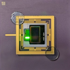
Built upon the Pregius 5.0 MPixel IMX250 CMOS sensor, the Sony IMX250MZR monochrome sensor incorporates a polarizer array that is positioned on-chip as opposed to on-glass above the imager. It comprises an air-gap nano wire-grid coated with an anti-reflection material that suppresses flaring and ghosting. The on-chip placement reduces polarization crosstalk and improves extinction ratios.
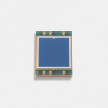
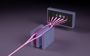
More specifically, the sensor sports a 2x2 pixel sub-array. Filters above each of the pixels within the sub-array filter light at a different polarization angle (0, 45, 90 or 135 degrees). Above each polarizer is an individual micro lens which focuses incoming light through the polarizer and onto each photodiode on the imager (Figure 2).

Figure 2: The Sony IMX250MZR monochrome sensor sports a unique 2x2 pixel sub-array. Filters above each of the pixels within the sub-array filter light at a different polarization angle (0, 45, 90 or 135 degrees). Above each polarizer is a micro lens which focuses incoming light through the polarizer and onto each photodiode on the imager. Image courtesy LUCID Vision Labs.
With the position of the polarizer array being on-chip and below each micro lens on the device, the polarization sensor reduces the crosstalk from light which may have (in on-glass type designs) been incorrectly detected by the wrong pixel.
Both the intensity of the light and the angle in which it is polarized is output from each pixel on the sensor. This data can then be interpolated to provide values for both the intensity and the degree and angle of linear polarization.
The design enables cameras built with the sensor to obtain images with four different polarization angles for every image that is captured. Firmware inside a camera can then enable a user to select and view images from each polarization angle individually or to save raw image files containing data from all four polarization angles. Selecting one angle, a user would see a resulting image of only one quarter of all of the pixels, but with the polarized light at one unique angle. If a user selects all of the pixels, the data can then be interpolated according to the demands of the application.
False color visualization is one method that can be employed to highlight the image intensity and angle of polarization from cameras equipped with the new sensor. Some camera manufacturers provide their own software development kits specifically for the purpose, while other may point their customers to third party software packages to process the data.
For its part, for example, FLIR provides what it calls the “SpinView” GUI which supports viewing polarimetry parameters as a map of angle of linear polarization and degree of linear polarization. The SpinView GUI can also display the output from individual angles of polarization as well as a composite image.
Innovative applications
The use of cameras equipped with polarization filters can be employed to help define edges in low contrast areas for robotics and bin picking, finding edges on very reflective materials touching each other, and determining the stress in plastics and glass.
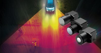
On-sensor polarization enables dynamic reduction of glare and reflections and is useful in outdoor environments where control of lighting conditions is not possible. Traffic systems can use cameras equipped with the Sony sensor to remove reflection on car windows, distinguish direct light from reflection and to achieve better shape-recognition in low-contrast conditions.
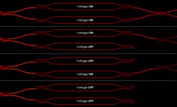
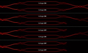
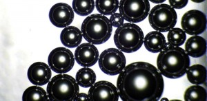
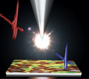
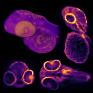
When polarized light passes through transparent materials, the incoming angle of polarized light will be changed to a different angle by different areas of stress in the object. By assigning a color to specific angles of polarization, defects and areas of stress can be visualized. Food inspection applications can also benefit from the use of polarizers by reducing reflection and glare. In low light situations, contrast can be improved by detecting the angle of polarization off objects (Figure 3).


Figure 3: When polarized light passes through transparent materials, the incoming angle of polarized light is changed to a different angle due to different areas of stress in the object. By assigning a color to specific angles of polarization, defects and areas of stress can be visualized (top). Objects can reflect light and make it difficult for surface inspecting. Food inspection applications can benefit from the use of polarizers by reducing reflection and glare (center). In low light situations, contrast can be improved by detecting the angle of polarization off objects (bottom). Image courtesy LUCID Vision Labs.
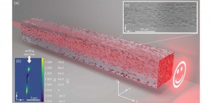
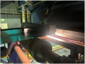
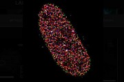
In one recent application, researchers from the Fraunhofer Institute for Integrated Circuits IIS demonstrated how a LUCID Phoenix polarization camera featuring Sony’s IMX250MZR CMOS polarized sensor had been used to inspect carbon fiber (Figure 4).

Figure 4: Researchers at the Fraunhofer Institute for Integrated Circuits IIS have demonstrated how LUCID Vision Labs’ Phoenix polarization camera featuring Sony’s IMX250MZR CMOS polarized sensor can be used to inspect carbon fiber. Image courtesy LUCID Vision Labs.
One of the unique properties of carbon fibers is that they polarize incidental unpolarized light parallel to the direction of the fiber. In their demonstration, the Fraunhofer researchers showed how the camera had been employed to capture the orientation and the position of the carbon fiber bundle in real time, and how their own Polka Imaging software had been used to calculate the degree of linear polarization, which directly indicated the direction of the fibers.
Written by Dave Wilson, Senior Editor, Novus Light Technologies Today