


Beam profile intensity distribution is an important parameter that indicates how a laser beam will behave in an application and will dictate the overall system performance in a specific setup. A laser propagating through space has a different width and spatial intensity distribution along its propagation path. This is continuously changing as a function of its laser cavity, divergence, interaction with optical elements and electronics driver characteristics. Although existing theory accurately predicts laser propagation in a real world involving engineering specification, it is crucial for researchers, system designers, and laser manufacturers to be able to accurately measure these parameters. ISO standard 11146 defines approaches to be used in measuring such beams.
Beam profile definition
Laser beam profile perpendicular to its propagation direction is not defined, and in theory extends to infinity. The commonly used definition of beam width is the width at which the beam intensity is 1 /e2 (13.5%) of its peak value. This value is derived from the propagation of a Gaussian beam and accurately describes the beam’s distribution for lasers operating in the fundamental TEM00 mode.
However, many lasers are close enough to a Gaussian approximation and applying this simple definition is a common practice in the industry. Another more accurate definition is found as well in the IS011146 standard, which specifies the beam width at the second moment. The point of the second moment is a value that is calculated from the raw intensity data and it is very sensitive to measurement noise as well as to random laser noise. A third way is calculated from the beam’s integral and it is free of noise problems and known as the knife-edge method.
Technologies for measuring beam width
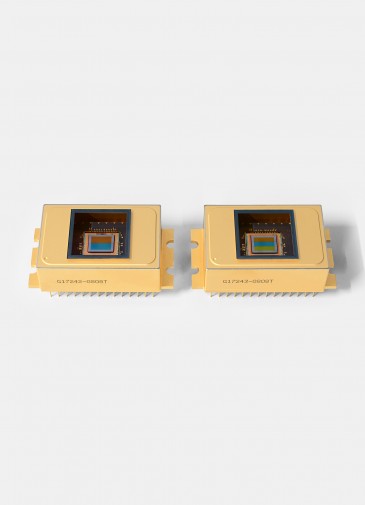
There are four main types of beam-profiling measurement instruments: Camera-based systems, knife-edge scanners, slit scanners and pinhole scanners. Each has specific advantages and disadvantages. A fifth type was introduced by Duma Optronics, and it falls between knife-edge technology and a camera-based system. Different measurement techniques may result in slightly different results. As a rule of thumb, measuring a pulsed laser beam is best when performed with CCD beam profilers that offer superior performance when compared with CMOS technology. On the other hand, measuring a CW laser beam is best when using the knife-edge technologies, especially along with the tomographic reconstruction procedure.
Camera-based profilers
Camera-based profilers use a two-dimensional mosaic array to instantly record and display the entire laser beam distribution that impinges on the camera surface. The intensity distribution of a laser beam is recorded pixel by pixel and is displayed as either a topographic or three-dimensional contour plot. The image generated is interfaced to a computer, followed by two- and three- dimensional profile plots and full beam analysis software. Cameras can be used with both CW and pulsed laser beams. The main disadvantage of these instruments is that their measurement resolution is limited by pixel size (usually between 5 and 10 micrometers), which, in general, limits their use in measuring beams smaller than 60 micrometers in width.
A new class of camera-based profiler, the MicroBeam, overcomes this size limitation by magnifying the laser beam, in a calibrated manner, by a factor of up to x100. This allows profiling of beams less than 0.5 micron in diameter, but limits the maximum beam diameter to about 50 micrometers.
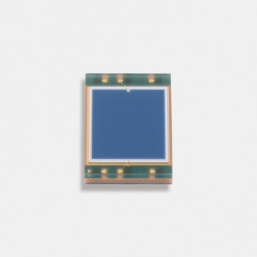
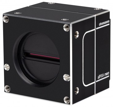
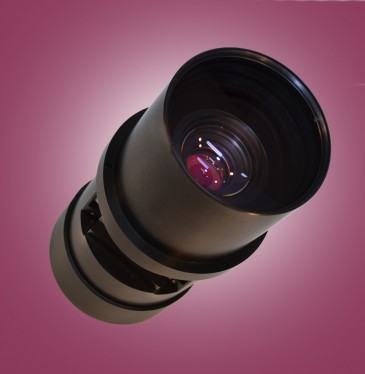
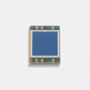
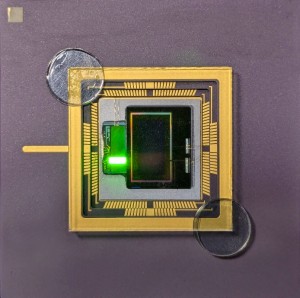
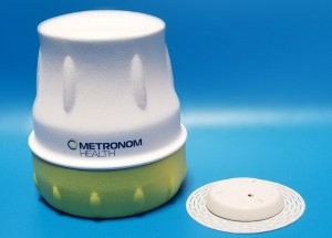
A special phosphoric coated CCD beam profiler will measure up to 1550 nanometers. High end beam profilers such as BeamOn HR-AFW are offered with a built in automatic filter wheel (Photo 1).
Knife-edge tomographic profiler
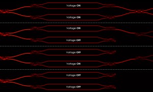
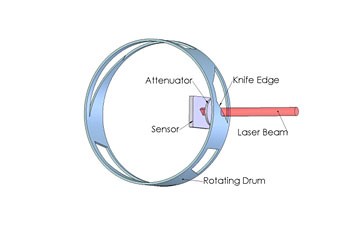
This instrument generates the profile by mechanically moving a knife edge across the beam, dynamically obstructing the amount of laser energy impinging the detector area. The profile is then calculated from the knife-edge speed of movement and its correlation to the detector’s energy reading. Unlike other systems our proprietary scanning technique allows several knife edges, each one differently oriented to sweep across the beam. Each knife edge will yield a different profile corresponding to its scanning direction. The various profiles are mathematically processed using tomographic algorithms to generate an image distribution similar to the images produced by CCD cameras.
The knife-edge scanning systems are known to be very accurate, with measuring capabilities of down to a few microns and up to several mm as standard. Their sensitivity ranges from 190 nanometers up to 2700 nanometers.
Scanning knife edge in depth
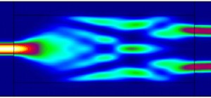
Knife-edge profilers use an aperture large enough to enable the entire beam pass. The aperture has one sharp, straight edge (knife edge). As the aperture traverses the beam, the system measures the portion of the beam that is not blocked by the blade (Figure 1) and plots the differential (rate of change in intensity) versus location of the power through the aperture. As the knife edge passes through the beam, the system approximates the beam size and a sophisticated electronic circuit samples across the beam 8000 times per sweep, to be further processed to yield about 1000 useful points per profile regardless of beam size. Very small beams in the micron region are sampled with lower resolution. This auto zooming procedure offers the highest possible accuracy independent of beam size.
Tomographic scanning
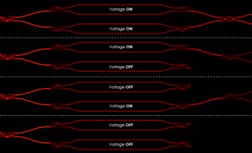
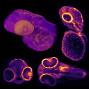
As discussed above, scanning slit and knife-edge scanners cannot generate truly accurate 3D reconstructions of laser beam profiles. Reasonable approximations can be made, however, by using tomographic techniques—the same techniques used with MRI and CAT scanners to create 3D images of internal organs. The key to making these reconstructions is to scan the beam in as many different directions as possible. For useful tomographic analysis, scans from at least three different directions are needed. If scans could be made from 10 or more directions, the 3D reconstruction would have been highly accurate.
Mechanics of a knife-edge beam profiler
In today’s engineering world, many new applications of material processing using lasers have emerged. In particular fiber laser technology has made a dramatic progress in output power and beam quality. Kilowatts of power have been demonstrated and implemented for various applications such as cutting, welding, ablating and others. The advantages of fiber lasers are their high power mechanical stability and good beam quality; however beam quality and profile has to be periodically checked.
In general, there are many difficulties in checking beam quality especially at the focal point, where densities will exceed 50KWatt per square cm. On one hand those energies are capable to melt and destroy most known materials, while on the other hand, measuring focused profile is the most significant measurement.
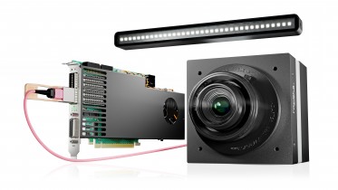
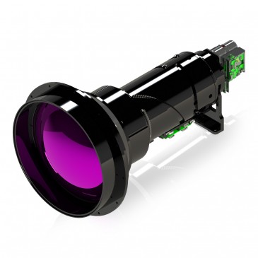
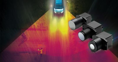
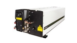
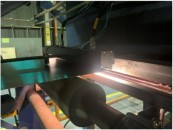
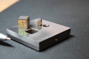
Recent developments have been made in the area of distortion-free, accurate beam sampling. A carefully designed Beam Sampler can sample about 1/100000 without distortion, while preserving the original beam polarization. Photo 2 shows a typical application of a laser welding line used on the automotive industries.
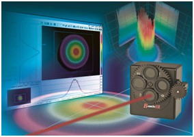
Photo 1: CCD Beam profiler - Duma BeamOn HR AFW
")
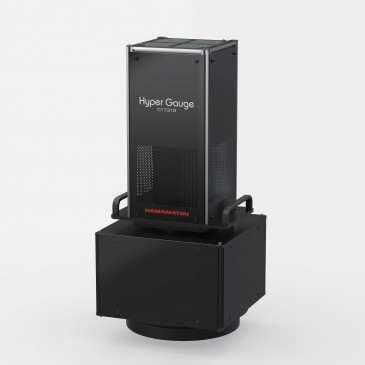
Photo 2: Knife-edge beam analyzer with sampler for high power laser measurement (up to 1.5kW)
Written by Oren Aharon, Chief Technology Officer of Duma Optronics Ltd. based in Nesher, Israel.