


Tier 1 suppliers play a vital role supplying automobile OEMs with critical subassemblies they need to build vehicles in contemporary just-in-time manufacturing environments. In many cases, Tier 1 suppliers perform the entire design and development of intricate subassemblies, creating fully working prototypes before producing, assembling and delivering finished items directly to an automotive production line.
Prior to installation on a vehicle, each subassembly must be inspected to ensure that it meets the stringent quality requirements demanded by the automobile manufacturer. In the past, such inspections were performed manually, but over the past twenty years, increasing numbers of automobile manufacturers have deployed vision systems to automate the task.
When one prestigious UK-based Tier 1 automobile manufacturer was faced with the challenge of inspecting front consoles as a final inspection before delivery to the automobile manufacturer, it contacted engineers at Didcot, Oxford-based Industrial Vision Systems (IVS) to develop a robotic-based vision system specifically for the task.
Traditionally, many such vision systems have comprised a set of cameras mounted at fixed positions on a bespoke frame, and were positioned to capture relevant images of the parts of the subassemblies as they entered an inspection cell. The vision system then processed the images in software to determine whether any aspect of the subassembly failed to meet the required quality standards.
Deploying robotics-based vision systems
However, according to Earl Yardley, the Director of IVS, the decreasing cost of robots now enables less expensive, yet more flexible, vision systems to be developed and deployed.
“These vision-based robotic work cells typically comprise one or more robots with both cameras and lighting mounted on their end effectors. The result is that the system can be quickly reprogrammed to inspect many different variants of products. To set up such a system, we move a machine vision camera on the end of the robot end effecter around to the position on the subassembly where the relevant features need to be checked. Once the features have been selected on a specific subassembly, the robotic vision system software can then be programmed to inspect the locations on any subsequent product presented to it,” he said.
The center console subassemblies supplied to the automobile manufacturer are complex products in their own right. They include a variety of storage compartments, such as glove boxes, as well as provide a surface to which a variety of different types of instrumentation, such as switches, entertainment and guidance systems are fitted. When the console is mounted onto to the vehicle, a gasket on the underside of the unit provides a seal between the surface of the console and the body of the vehicle itself.
Performing critical inspections
According to Mr. Yardley, the Tier 1 automotive manufacturer needed to perform a number of checks on the outgoing consoles as a final inspection before delivery. These included checking that the gasket was fitted correctly, performing gap and flush inspection to determine the fit and alignment between different elements on the console, as well as checking the color and logos on the switches mounted to the console.
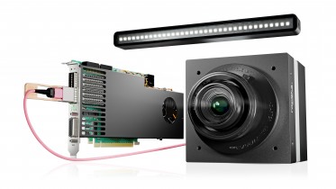
“To perform those functions, IVS developed a system based around a Universal Robot that was fitted with one GigE monochrome and one GigE color camera (IVS-NCGi-1920-43M & IVS-NCGi-1920-43C) -- which were deployed individually according to the inspection tasks that needed to be performed -- while a pair of IVS custom LED lights were used to illuminate the parts of the assembly during the process,” said Mr Yardley.
In operation, an Automatic Guided Vehicle (AGV) first transports the console sub-assemblies into the robotic vision inspection cells where the automated inspection is performed by the robot. To do so, the robot arm positions the camera head at key positions around the part. Images from either the monochrome or color camera are then transferred over a GigE interface to an IVS industrial PC controller for analysis.
A thorough software check routine
The system PC runs the IVS software -- an integrated environment for the interactive configuration of visual inspection applications, which obviates the need for a developer to program the system in a low-level language. The visual point and click development environment enabled the IVS engineers to develop a software check routine that contained all of the vision inspection tasks that were to be performed hierarchically on the images of the console.
The vision system's Human Machine Interface (HMI) -- also developed by IVS -- provided an analysis of the inspected subassembly giving feedback to the operator highlighting the location of any flaws or omissions.

The IVS vision-based robotic inspection system performs a number of checks on the on the incoming consoles included checking that the gasket was fitted correctly, performing gap and flush inspection, as well as checking color and logos on the switches.
To ensure that the gasket on the console was fitted correctly, the monochrome camera is indexed around the subassembly and images of the gasket are captured at several key locations. Once the images have been transferred to the PC, the software finds the location of the edges of the gasket by comparing the positional measurements with known datum positions.
Gap and flush analysis
To measure the clearance between the various component parts that comprise the entire console, the IVS software performs what is known as a gap and flush analysis. This ensures that the fit and alignment of individual components within the assembly is correct in relation to the assembly environment itself.
To do so, color images of the subassembly are analyzed and the gaps between the component parts in the images are determined by threshold or edge detection operations. The distance between the gaps can then be measured, converted to real-world measurements and tolerances applied to them to determine whether the distances are within an acceptable range that meets the specifications demanded by the automobile manufacturer.
Due to the large variety of buttons and switches that could potentially be specified for the console of the automobile, it was also crucial for the manufacturer to determine that the appropriate button or switch was present on each unique unit and that that the correct symbol was applied to it.
Checking the buttons
The presence of each button is determined by a presence detection check routine. This routine finds the region of interest within the image where the buttons or switches are to be found, performs a threshold operation on the image to isolate the switches from the background and then verifies whether they are present or not.
To determine whether the correct logo or character has been applied to the button, the software uses either a pattern matching technique -- a method in which the system compares the image of the logo on the switch with a set of template images that it has previously been taught – or, alternatively character recognition.
To determine that the color of each part of the console meets specifications, a color matching technique was employed. Having taught the system acceptable ranges for several different types of reference colors, the software can then match those with the areas of different colors on the console. Using the system, the end user can define any number of reference colors in different shades and optimization of the reference colors is possible at any time.
Methods of illumination
The use of two LED lights mounted on the end effecter of the robotic arm enables the system to illuminate the fixtures on the console using either bright field lighting (where light is reflected into the camera) or dark field lighting (where it is reflected away). Bright field lighting is used in the system to capture high contrast images of areas such as the console gasket, whereas dark field lighting is used to capture images of textured surfaces, such as areas that may be covered in leather.
“Once the vision system has performed all the inspection tasks, the results of the inspection are highlighted on the dedicated HMI interface. If the console has passed the inspection, the Automatic Guided Vehicle transports the unit out of the inspection cell. If the console fails any of the inspections, the vehicle reverses the console out of the cell to a holding location where it can be manually inspected and any modifications to it performed before it re-enters the cell for further inspection,” said Mr. Yardley.
In addition, the color camera is used to capture a number of images of the complete console that are stored on the PC, together with unique bar code information identifying the unit. These images enable the automotive manufacturer to provide a visual indication of the integrity of the console to its customer.
Future proof
According to Mr. Yardley, the use of the IVS robot inspection cell has not only allowed a single vision machine system to inspect endless parts and variants, it has also made the inspection system future proof, so the automotive customer can add new components and modifications to the system capabilities at their leisure.
Written by Dave Wilson, Senior Editor, Novus Light Technologies Today