


In the field of research and development, thermal imaging cameras are an established tool for evaluating solar cells and panels. However, the use of thermal imaging cameras for solar panel evaluation is not restricted to the field of research. Uncooled thermal imaging cameras are currently being used more and more for solar panel quality controls before installation and regular predictive maintenance check-ups after the panel has been installed. Because these affordable cameras are handheld and lightweight, they allow a very flexible use in the field.
With a thermal imaging camera, potential problem areas can be detected and repaired before actual problems or failures occur. But not every thermal imaging camera is suited for solar cell inspection, and there are some rules and guidelines that need to be followed in order to perform efficient inspections and to ensure that you draw correct conclusions. The examples in this article are based on photovoltaic modules with crystalline solar cells; however, the rules and guidelines are also applicable to the thermographic inspection of thin-film modules, as the basic concepts of thermography are the same.
Procedures for inspecting solar panels with thermal imaging cameras
During the development and production process, solar cells are triggered either electrically or by the use of flash lamps. This ensures that there is sufficient thermal contrast for accurate thermographic measurements. This method cannot be applied when testing solar panels in the field, however, so the operator must ensure that there is a sufficient energy input by the sun.
To achieve sufficient thermal contrast when inspecting solar cells in the field, a solar irradiance of 500 W/m2 or higher is needed. For the maximum result, a solar irradiance of 700 W/m2 is advisable. The solar irradiance describes the instantaneous power incident on a surface in units of kW/m2, which can be measured with either a pyranometer (for global solar irradiance) or a pyrheliometer (for direct solar irradiance). It strongly depends on location and local weather. Low outside temperatures may also increase thermal contrast.
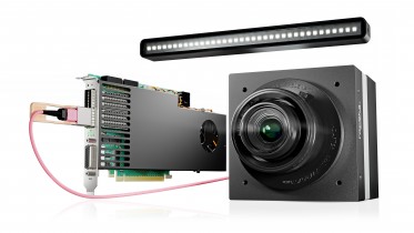
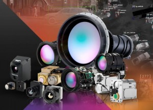
What type of camera do you need?
Handheld thermal imaging cameras for predictive maintenance inspections typically have an uncooled microbolometer detector sensitive in the 8–14 μm waveband. However, glass is not transparent in this region. When solar cells are inspected from the front, a thermal imaging camera sees the heat distribution on the glass surface. Only indirectly can it see the heat distribution in the underlying cells. Therefore, the temperature differences that can be measured and seen on the solar panel’s glass surface are small. In order for these differences to be visible, the thermal imaging camera used for these inspections needs a thermal sensitivity ≤0.08K. To clearly visualize small temperature differences in the thermal image, the camera should also allow manual adjustment of the level and span.
Photovoltaic modules are generally mounted on highly reflective aluminum framework, which shows up as a cold area on the thermal image, because it reflects the thermal radiation emitted by the sky. In practice that means that the thermal imaging camera will record the framework temperature as being well below 0°C. Because the thermal imaging camera's histogram equalization automatically adapts to the maximum and minimum measured temperatures, many small thermal anomalies will not immediately be visible. To achieve a high contrast thermal image continuous manual correction of the level and span would be needed.
The so-called DDE (Digital Detail Enhancement) functionality provides the solution. DDE automatically optimizes image contrast in high dynamic range scenes, and the thermal image no longer needs to be adjusted manually. A thermal imaging camera that has DDE is therefore well suited for fast and accurate solar panel inspections.
Useful features
Another useful feature for a thermal imaging camera is the tagging of thermal images with GPS data. This helps to localize faulty modules easily in large areas, e.g., in solar farms, and also to relate the thermal images to the equipment, e.g., in reports.
The thermal imaging camera should have a built-in digital camera so that the associated visual image (digital photo) can be saved with the related thermal image. A so-called fusion mode, allowing the thermal and visual images to be superimposed, is also useful. Voice and text comments that can be saved in the camera along with the thermal image are beneficial for reporting.
Positioning the camera, taking into account reflections and emissivity
Even though glass has an emissivity of 0.85–0.90 in the 8–14 μm waveband, thermal measurements on glass surfaces are not easy to do. Glass reflections are specular, which means that surrounding objects with different temperatures can be seen clearly in the thermal image. In the worst case, this results in misinterpretations (false "hotspots") and measurement errors.

This thermal image shows large areas with elevated temperatures. Without more information,it is not obvious whether these are thermal anomalies or shadowing/ reflections.
To avoid reflection of the thermal imaging camera and the operator in the glass, it should not be positioned perpendicularly to the module being inspected. However, emissivity is at its highest when the camera is perpendicular, and decreases with an increasing angle. A viewing angle of 5–60° is a good compromise (where 0° is perpendicular).
Long-distance observations
It is not always easy to achieve a suitable viewing angle during the measurement setup.

Viewing angle recommended (green) and to be avoided (red) during thermographic inspections.
Using a tripod can provide a solution in most cases. In more difficult conditions it might be necessary to use mobile working platforms or even to fly over the solar cells with a helicopter or drone.

Thermal image made using a FLIR P660 camera on a flight over a solar farm. (Thermogram courtesy of Evi Müllers, IMM)
In these cases, the longer distance from the target can be advantageous, since a larger area can be seen in one pass. To ensure the quality of the thermal image, a thermal imaging camera with an image resolution of at least 320 × 240 pixels, preferably 640 × 480 pixels, should be used for these longer distances.
The camera should also have an interchangeable lens, so the operator can switch to a telephoto lens for long distance observations. It is advisable, however, to only use telephoto lenses with thermal imaging cameras that have a high image resolution. Low resolution thermal imaging cameras will be unable to pick up the small thermal details that indicate solar panel faults in long distance measurements using a telephoto lens.
A different perspective
In most cases installed photovoltaic modules can also be inspected with a thermal imaging camera from the rear of a module. This method minimizes interfering reflections from the sun and the clouds. In addition, the temperatures obtained at the back may be higher, as the cell is being measured directly and not through the glass surface.
Ambient and measurement conditions
When undertaking thermographic inspections, the sky should be clear because clouds reduce solar irradiance and also produce interference through reflections. Informative images can, however, be obtained even with an overcast sky, provided that the thermal imaging camera used is sufficiently sensitive. Calm conditions are desirable, since any airflow on the surface of the solar module will cause convective cooling and thus will reduce the thermal gradient. The cooler the air temperature, the higher the potential thermal contrast. Performing thermographic inspections in the early morning is an option.
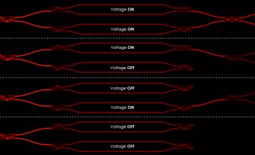
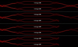
Another way to enhance thermal contrast is to disconnect the cells from a load, to prevent the flow of current, which allows heating to occur through solar irradiance alone. A load is then connected, and the cells are observed in the heating phase.
Under normal circumstances, however, the system should be inspected under standard operating conditions, namely under load. Depending on the type of cell and the kind of fault or failure, measurements under no-load or short-circuit conditions can provide additional information.
Measurement errors
Measurement errors arise primarily due to poor camera positioning and suboptimal ambient and measurement conditions.

List of typical module errors. (Source: ZAE Bayern e.V, “Überprüfung der Qualität von Photovoltaik- Modulen mittels Infrarot-Aufnahmen” ["Quality testing in photovoltaic modules using infrared imaging”], 2007)
Typical measurement errors are caused by:
- too shallow viewing angle.
- change in solar irradiance over time (due to changes in sky cover, for example).
- reflections (e.g., sun, clouds, surrounding buildings of greater height, measurement setups).
- partial shadowing (e.g., due to surrounding buildings or other structures).
What you see in the thermal image
If parts of the solar panel are hotter than others, the warm areas will show up clearly in the thermal image. Depending on the shape and location, these hot spots and areas can indicate several different faults. If an entire module is warmer than usual that might indicate interconnection problems.

This thermal image shows an example of the so-called ‘patchwork pattern’, which indicates that this panel has a defective bypass diode.
Shadowing and cracks in cells show up as hot spots or polygonal patches in the thermal image. The temperature rise of a cell or of part of a cell indicates a defective cell or shadowing.

These red spots indicate modules that are consistently hotter than the rest, indicating faulty connections.
Thermal images obtained under load, no-load, and short-circuit conditions should be compared. A comparison of thermal images of the front and rear faces of the module can also give valuable information.

This hot spot within one solar cell indicates physical damage within the cell.
Of course, for correct identification of the failure, modules showing anomalies must also be tested electrically and inspected visually.
Correct and informational images
The thermographic inspection of photovoltaic systems allows the fast localization of potential defects at the cell and module level as well as the detection of possible electrical interconnection problems. The inspections are carried out under normal operating conditions and do not require a system shut down.
For correct and informative thermal images, certain conditions and measurement procedures should be observed:
- a suitable thermal imaging camera with the right accessories should be used;
- sufficient solar irradiance is required (at least 500 W/m2 – above 700 W/m2 preferred);
- the viewing angle must be within the safe margins (between 5° and 60°);
- shadowing and reflections must be prevented.
Thermal imaging cameras are primarily used to locate defects. Classification and assessment of the anomalies detected require a sound understanding of solar technology, knowledge of the system inspected, and additional electrical measurements. Proper documentation is, of course, a must, and should contain all inspection conditions, additional measurements, and other relevant information.
Inspections with a thermal imaging camera - starting with the quality control in the installation phase, followed by regular checkups - facilitate complete and simple system condition monitoring. This will help to maintain the solar panels' functionality and extend their lifetime. Using thermal imaging cameras for solar panel inspections will therefore drastically improve the operating company’s return on investment.
Written by Ruud Heijsman - Public Relations Manager EMEA at FLIR Systems.