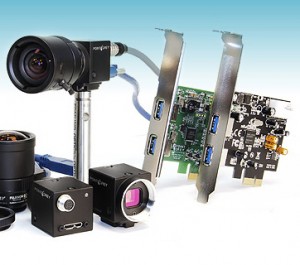
A new industrial vision standard based on USB 3.0 looks set to make its mark as one of the most successful interfaces in the machine vision industry since the introduction of GigE Vision. Indeed, many companies are now betting that the new USB3 Vision standard and GigE Vision will be the two dominant standards in the machine vision market over the next five years.
Transfer rate of more than 350 megabytes per second
One of the appealing features of the USB 3.0 standard itself is its throughput, or the rate at which image data can be transferred over the bus. While earlier incarnations of the USB standard, such as USB 1.0 and USB 2.0 had relatively low throughputs compared to many established vision interfaces such as Firewire and Cameralink, USB 3.0 provides a transfer rate of greater than 350MB per second.
USB 3.0 also uses asynchronous signaling, which allows a device such as a camera to notify a host PC when it is ready to transfer data. This reduces system overhead and CPU usage compared to the polling mechanism used in the earlier USB 2.0 specification.
However, recognizing that additional features needed to be added to make the USB 3.0 interface applicable to developers of industrial vision systems, a group of camera, software, cable and IP companies has developed an extension to the USB 3.0 standard specifically for that purpose. Working under the auspices of the Automated Imaging Association (AIA), the USB3 Vision specification they created was ratified in February 2013.
The Superspeed spec
According to Thies Möller, Technical Architect at camera maker Basler based in Ahrensburg (Germany), the USB3 Vision standard is built upon the USB 3.0, or “Superspeed” USB specification. But it also defines a new mechanical specification as well as a means by which devices such as cameras can be identified and controlled over the USB 3.0 bus, and a mechanism used to stream data from them.

In addition to the standard connectors specified by the USB 3.0 standard, USB3 Vision specifies screw lock connector versions of the standard connectors. These provide systems integrators with an assurance that their USB 3.0 Vision cameras can withstand the vibration and rotation commonly found in industrial vision systems.
To provide backward compatibility with USB 2.0, the USB 3.0 cable sports an unshielded twisted pair of cables. But to support full duplex transmission, the USB 3.0 cable also has two additional shielded twisted pairs -- one for transmit and one for receive. The result is that data can be transferred to and from a camera to a host computer, while issues with electro-magnetic interference (EMI) from any external sources are reduced.
Cable length
Unlike many other interface standards such as Firewire and Gigabit Ethernet, the USB 3.0 specification upon which the USB3 Vision standard is built does not specify a maximum length of cable that can be used to connect a camera to a computer. Rather, the specification defines a maximum voltage drop from one end of the cable to the other that must be adhered to, a specific signal strength that must be received to maintain a low error rate, and a defined maximum propagation delay for signals.

To provide backwards compatibility with USB 2.0, the USB 3.0 cable sports an unshielded twisted pair of cables. But to support full duplex transmission, the USB 3.0 cable also has two additional shielded twisted pairs -- one for transmit and one for receive.
USB 3.0 cameras with a power rating of 4.5W (at 5V) can be supported by the standard, and passive cables have been tested at up to 8m in length. Although that distance might pale in comparison to the 100m lengths achievable with the GigE Vision standard, many active extenders are now coming onto the market that will boost USB 3.0 reach to comparable distances.
To identify a camera and its attributes, such as gain, resolution and speed, USB3 Vision has taken a leaf from the GigE Vision standard, using the GenApi module of the GenICam standard to enable camera features to be accessed from an XML file on the camera itself. The USB3 Vision standard also uses part of the GenICam standard known as the Generic Control Protocol (GenCP) to control the operation of the camera, enabling commands to be sent to it to acquire and transmit data.
The USB 3.0 standard also features a bulk transfer mode that supports error detection and re-transmission mechanisms to ensure that data is transmitted and received without error. Building on top of that, the USB3 Vision committee developed the USB3 Vision Streaming Protocol that defines a software mechanism that cameras can use to send image data and other protocol information to a host.
Streaming protocol
According to Basler’s Möller, the Streaming Protocol mechanism ensures that the camera and the host that it is connected to work at maximum efficiency. To do so, the protocol obviates the need for any unnecessary copying of data on the host PC and the related use of processing power and memory bandwidth.
This is achieved through the use of a “zero-copy DMA mode”, which enables image data from a camera to be transferred directly under control of the USB controller chip on a PC to the PC memory with minimal CPU intervention. The protocol also enables images of variable size to be defined in the data packets that are sent from the camera to the PC. In use, a camera can send a smaller or a larger image frame over the bus without the host knowing in advance.
Once in memory, the image data can be directly accessed by a user’s image processing application.
The streaming protocol is one of the biggest advantages of the USB3 Vision standard versus alternative means of transferring video data from a camera to a host. Although the USB 3.0 standard itself defines a class of devices (such as webcams) that can stream video data, the methodology does incur a greater CPU overhead than the zero-copy DMA mode developed by the USB3 Vision committee.
Future additions
Albeit the fact that the USB3 Vision standard has been completed, Basler’s Möller says that the USB3 Vision committee is now working on important additions. The committee aims, for example, to define a mechanism that will enable multiple cameras to be synchronized – an important issue in applications such as 3D vision where system integrators must ensure that two cameras acquire images at precisely the same instant in time. Although such synchronization can currently be achieved using hardware triggers, the committee now plans to develop a means to accomplish the task in software.
The committee also intends to define a means by which multiple image streams from a single camera can be transferred across the bus. This will benefit those systems integrators who currently use single cameras to capture several regions of interest (ROIs) in an image and may need to stream data from those ROIs over the bus at different times or at different rates.
Plans are also afoot to create a way to lower the CPU overhead incurred with processing the image data at the host. Although the zero copy DMA mechanism itself reduces the amount of CPU intervention incurred during the transfer of images from a camera to a host, in certain applications, that overhead can still prove a burden.
Möller says that this is especially true in high-speed image processing systems where relatively small images are captured and transferred over the bus at rates of over 30,000 times per second. In these circumstances, the CPU overhead involved in processing the ancillary data associated with the image data (such as its type and size) can become more significant.
Ideas are also being proposed to make the USB Vision standard more deterministic. At the present time, asynchronous events from a camera (such as those that indicate that it has captured an image, or that it has started to transmit image data) are transferred over the bus using the USB 3.0 bulk transfer mode. However, in certain circumstances, such as when the bus becomes saturated with large mounts of video data, systems integrators cannot be assured that the time that it takes such events to arrive at the host can be guaranteed. Hence the USB Vision committee is examining ways in which the interrupt transfer mechanism defined in the USB 3.0 specification might be used to transfer such event data, thereby guaranteeing its delivery time.
Validation suite
Many systems integrators will, of course, be concerned with whether the cameras that they specify for their machine vision applications meet the USB3 Vision specification. To alleviate their concerns, Möller says that the AIA has developed a USB3 Vision validation suite specifically for the purpose.
This software suite enables camera vendors to test their USB 3.0 cameras to ensure that they meet the specification. In addition, vendors who claim that their cameras comply with the USB 3.0 Vision standard must also attend so-called “Plug-Fests” where they must demonstrate that their cameras are compatible with a number of different hosts and applications software. Once validated, the cameras can carry a USB3 Vision logo, providing systems integrators with some assurance that they meet the specification.
Written by Dave Wilson, Contributing Editor, UK, Novus Light Technologies Today














 Back to Features