

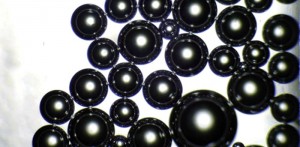


Laser interferometry is a widely established method for measuring the shape and surface quality of large telescope mirrors. Dynamic Interferometry, developed by 4D Technology Corporation, is an improved method in which all measurement data is acquired simultaneously, rather than over several frames and several hundred milliseconds. This technology enables measurement of large mirrors even in the presence of vibration and air turbulence, without expensive isolation equipment.
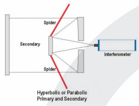
This is the case, for example, when testing a telescope with secondary and tertiary mirrors, or when testing a hyperbolic or parabolic primary and secondary as a system.
4Sight analysis software provides an extensive toolset for measuring mirrors partially obscured by support structures.
In these measurements the “spider” support structure obscures portions of the pupil, dividing the data into several islands. These discontinuities pose a challenge for phase unwrapping algorithms, potentially leading to phase ambiguities that can result in integral wave piston errors between data islands. These steps must be removed before the surface shape can be determined.
To date, these steps have been removed manually, with an operator adjusting the piston of the islands one at a time following each measurement. This technique works reasonably when dealing with a few measurements. When a large number of measurements must be handled, however, manual adjustment becomes time-consuming.
The problem becomes much more critical when working with averaged measurements. Averaging improves measurement repeatability by lessening the impact of quasi-random environmental effects (primarily air turbulence) and smaller effects such as camera noise.
When measuring large mirrors, with long stand-off distances, averaging is essential to account for air movement and thermal variations.
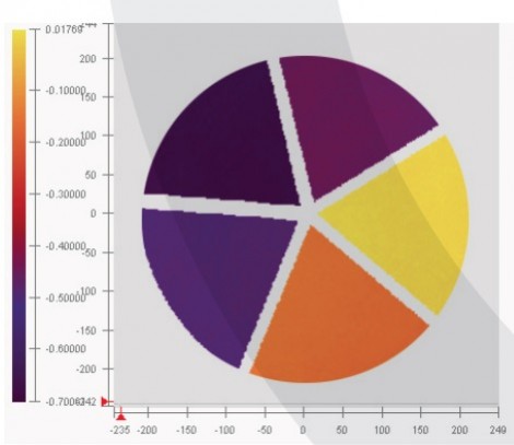
If one were to take an average of 64 measurements, phase ambiguities would lead the phase unwrapping algorithms to adjust a particular island up ½ wave in one measurement, perhaps down the next, and so on. When these differences are tallied up in the average, the result is non-½ wave steps that cannot be resolved automatically or manually (Figure 2).
4SightTM analysis software, supplied with all 4D dynamic interferometers, offers a number of tools for defining islands, resolving phase ambiguities, and even bridging obscured data in order to accurately measure large mirrors. The following sections will explain more about these tools and how they are used for making accurate average measurements.
Defining Islands
The first step in measuring a partially-obscured mirror is to define the data islands. In 4Sight, islands can be defined by modulation and intensity thresholds, or, often with better repeatability, by applying a user-created mask. Masks can be built up from multiple shapes. The “Spider” mask shape in particular lets you choose the number, width and angle of the legs of a supporting structure (Figure 3).
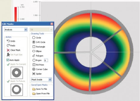
A spider mask provides a very consistent method for defining the regions that are obscured by a spider, across individual measurements and across each measurement in an average. The mask can be rotated to match the part instead of the part needing to be rotated to match the mask.
Island Levelling
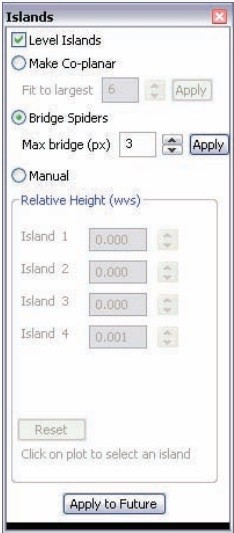
As mentioned earlier, after data is separated into islands there will likely be erroneous, ½ wave steps between some islands due to the ambiguities in phase unwrapping. 4Sight includes three Island levelling options under Modify > Islands > Level Islands (Figure 4) that allow you to adjust the heights of islands relative to each other to represent the true surface shape.
The Make Co-Planar method is most effective when each individual island has tilt and piston but minimal shape. The algorithm removes tilt from the largest islands, adjusts the piston of all islands until they are nearly equal in height, then restores the global tilt.
If the mirror under test has significant shape, a better choice is the Bridge Spiders option, which uses the following algorithm to carry the local slopes across the missing spider pixels:
- The slope at each pixel is determined by calculating the derivative of the trimmed surface in X and Y.
- Slope data is filled in across the spider legs to achieve continuous local slopes. The user controls how large of a gap can be bridged.
- The data-filled X and Y slopes are integrated to recover the corrected surface. This is done by starting with one pixel and using a flood-fill integration, to ensure that all pixels are co-referenced.
- The corrected surface is used to determine the piston between islands.
- The piston values are rounded to the nearest ½ waves.
- The piston of each island is adjusted accordingly
In some cases extreme shape or data spikes may make it difficult for the automatic routines to level islands. In these cases the Manual island levelling method can be used. Click on each island in the contour plot—its Relative Height will appear in red in the Level Islands dialogue box. Clicking the up and down arrows adjusts the island’s piston. A 2D profile or 3D display can aid you in determining the correct heights.
Equalising Islands
When making averaged measurements one additional processing step is required. As mentioned earlier, the unwrapping algorithms will attempt to force a particular island in each measurement up or down to ½ wave multiples. For one individual measurement in an average, island A might be higher than island B, but in the next island B may be higher than A. This can result in phase differences between the measurements.
Although 4Sight cannot resolve this ambiguity, the Equalise Islands option (under Measure > Measurement Options > Averaging) will make the height of each island consistent for each measurement within the average. The island height in the final average may be offset by a ½ wave due to the fundamental ambiguity, but there will be no fractional steps between islands, so processing can continue
Aberration Removal
Piston, tilt, power, etc, can be removed from the entire dataset by choosing Analysis > Aberration Removal. Higher order terms can be removed using 4Sight’s Zernike Worksheet or Zernike Table.
In some cases removing terms before levelling the islands improves the process. In other situations, particularly when the test mirror has large aberrations or deviation from ideal, it may be best to level islands first and then remove terms. NOTE: A separate option in 4Sight enables aberration removal from each data island independently (Analysis > Island > Per Island Aberration Removal). This option is intended for use with arrays of individual, discrete objects, such as micro-mirrors in an array. It should NOT be used with spider measurements, in which we know a priori that the terms are essentially the same for all islands.
An Example Measurement
Figure 5 shows the effects of each of the above steps for accurately measure the primary, 200mm mirror in a Cassegrain telescope.
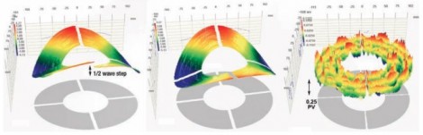
The left image shows the data as measured; half-wave steps are clearly visible. In the second pane the Bridging method was used to level the islands. In the third panel, the Zernike Worksheet was employed to remove 35 annular Zernike terms from the data, revealing the surface shape
Written by Mike Zecchino, Marketing and Technical Communications at 4D Technology Corporation