


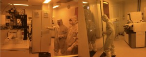


Illumination is a critical component of machine vision systems because it determines how the object being imaged appears to the camera. LEDs are the most widely used illumination source, and while factors such as the direction, wavelength and intensity of illumination all have a key role to play, precise control of the lighting can be crucial. Dedicated lighting controllers offer a number of benefits including maintaining consistent light levels, pulsing lights for high speed imaging, overdriving LEDs for enhanced intensity output and the establishment of sophisticated lighting sequences.
Maintaining consistent light levels
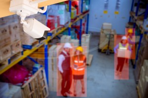
Machine vision systems are used to monitor, regulate, check, analyse, sort and classify, with high precision and repeatability. Consistent light levels are essential to guarantee repeatable results. Factors that can affect the illumination intensity include both the age and temperature of the LED, the effects of ambient light, and external factors such as dust and dirt which may reduce the amount of light reaching the object. Since LED light output is directly proportional to current, LEDs should be controlled by current, not voltage. This is because a very small change in voltage will cause a much larger change in brightness; for example, a 1% decrease in voltage will cause a 10% reduction in light output. This is a critical factor since even for a simple vision caliper measurement, a 10% reduction in light level can cause a change of 0.5% in the measured values which would be unacceptable in many industries where allowable reject levels are of the order of only 1 in 100,000 or better. One practical example of the effects of changes in light intensity occurred recently on a machine vision system that began rejecting good parts and accepting bad parts after a year in use. This was because the light intensity had dropped as the light had aged. Fortunately, the installed, current driven lighting controller supported ethernet connectivity, so the brightness could be readily adjusted to compensate for this via remote access without the cost associated with an on-site visit.
Enhancing LED output intensity
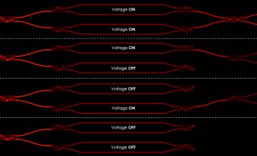
Current control provides stable and highly repeatable LED light output. However there are many applications where running the light continuously, even at 100% output doesn’t deliver enough light for accurate measurements. One solution is to ‘overdrive’ the LED to boost the output, although the lights can only be overdriven in pulses to prevent damage. By controlling the pulse width, frequency and intensity, precise control of the overdriving and the resulting light intensity is possible. This is illustrated by a vision system that was originally designed with the lighting controller operating the LED continuously at 100% brightness. During commissioning ambient light was found to interfere with the images, so more light from the LED was needed. The controller configuration was changed from continuous operation to overdrive pulsing for 200% brightness and the camera exposure shortened, meaning that the problem could be solved quickly without hardware changes.
High-speed imaging
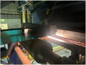
Another massive benefit of pulsing, or strobing the light source is to freeze the image of moving objects, particularly at high speeds, where overdriving may also be essential to deliver sufficient light intensity for the short camera exposure times. This is perfect for automating vision inspection on busy production lines. A fine adjustment of the pulse timing in the lighting controller is often more flexible than adjusting the camera’s timing. The camera can be set for a longer exposure time and the light pulsed on for a short time to freeze the motion. The flexibility to choose the sequence for camera and lighting controller triggering means that a whole range of applications can be accommodated, with or without external triggers from product position sensors on the production line.
Illumination sequencing
This versatile approach to camera and lighting controller triggering can further be extended to allow multi lighting schemes to be used. For example, a number of different measurements may be needed on an individual product at a particular point in the production process. This can be achieved by acquiring multiple images with a single camera using several lights operating under different lighting schemes. A dedicated lighting controller can trigger the lights at different intensities and for different durations in a defined sequence. This can eliminate the need for multiple cameras, saving both on cost and space. It is also possible to use multiple lighting schemes with line scan imaging, where information from different illumination sources can be captured on sequential lines and individual images for each illumination source extracted using image processing software.
High-speed synchronisation of machine vision devices
The use of a dedicated lighting controller can significantly improve both the performance of a machine vision system and the scope of applications. However, this can be even further extended when used with a specialist trigger timing controller such as Gardasoft’s CC320 unit which offers the functionality of a high performance PLC in a format ideal for machine vision applications. This provides high speed synchronisation and sequencing of machine vision devices through flexible triggering of lights, lighting controllers, cameras, proximity sensors, encoders and reject gates to generate an automated production line solution. High speed inspection, product arriving at regular or irregular intervals and the acquisition of multiple images using multiple light sources and/or multiple cameras can all be handled in this way. With eight independent input channels, the controller can take a range of input signals from various components and use these to trigger events on any of the eight independent output channels. For lighting control and sequencing, this could involve direct control of the lights, or control of a lighting controller. One example of using this configuration in a multi-lighting application with a single camera is shown in the diagram. Multiple outputs are required from one trigger signal, so here a sensor on IP1 detects product presence. Four images need to be taken from one camera at 40ms intervals using four different lights. OP1, OP2, OP3, OP4 are used to output triggers to the lights and OP5 is used to trigger the camera. OP1 to OP4 are pulsed for 40ms in sequence. As each one is pulsed, OP5 is also pulsed for a short time to trigger the camera
Written by Jools Hudson, Gardasoft Vision Ltd.