


Organic light emitting diodes (OLED) recently entered the commercial product market a few years ago, and in that short time, OLED has rapidly expanded its scope of use.
OLED is predominantly applied to displays such as mobile phones or television screens. However, due to their numerous benefits such as high colour rendering, high efficiency and flexibility compared to standard light sources, OLED lighting becomes also a significant player in the market of general and special lighting step by step. Moreover, the ultra-thin device structure of OLED technology and the material properties are very suitable for large area surface-emitting elements on glass substrate as well as thin flexible foils. OLEDs will thereby open new perspectives for novel lighting applications. An especially attractive application is the potential to design colour-tunable light sources linked with interactive controlling functions for automobile or indoor lighting.
Organic light emitting diodes generally consist of several organic layers with a thickness of several hundreds of nanometer sandwiched between two electrodes (figure 1). Usually the organic layers and the metal top electrode are separately evaporated subsequently on top of a glass or flexible foil substrate coated with a transparent electrode, such as, indium tin oxide (ITO) which plays a role as bottom electrode.
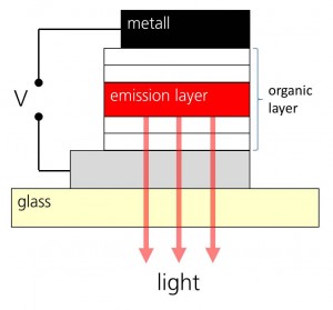
Figure 1: General layer structure of an organic light emitting diode
The emission colour of the OLED is defined by chosen emitter materials. Thereby various monochrome colours or white light can be produced. To realise white light emission, different emitter materials have to be mixed. This mixing can be realised via four different methods: (a) mixing of different emitter molecules within one emission layer, (b) deposition of multiple emitter layers on top of each other in one OLED unit, (c) vertically stacking of several OLED units having its own emitter material in each emission layer and (d) fine lateral structuring of monochrome OLEDs and mixing of the produced light with an optional combination of a scattering film on top for better homogeneity.
In general these methods can be used to accomplish colour-tunable OLED devices. However, for alternatives (a) and (b) this is only possible to some extent due to the restricted working principle based on only two electrodes, which means that the current is always flowing vertically through the whole OLED stack. For methods (c) and (d), an vertical and horizontal alignment of OLED structures, more freedom to generate intended colour is given by independent current feedings to each OLED unit (vertically) or OLED segment (horizontally).
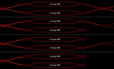
Fraunhofer COMEDD recently developed colour-tunable OLED devices using the vertically stacking of single OLED units (figure 2 at top). Especially, large colour-changeable lighting areas can be realized without the use of expensive lithographic steps. Furthermore, these modules show a higher fill factor compared to horizontally structured devices because every single colour unit is illuminating with the whole active area of the device. Besides, no scattering foil is necessary to archieve homogenious mixed light.

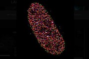
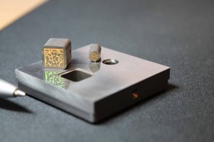
Figure 2: Colour-tunable OLEDs with an active area of 60 cm
Different colour mixtures can be realized by a controlled modulation of brightness of each OLED unit. Figure 2 is showing one module at different colours as the result of separate operation of each OLED unit (blue or yellow) or operation of both OLED units simultaneously (white).
2-unit/2-colour tunable modules
The simplest way to generate white light is the combination of the two emission colours blue and yellow. Here, a yellow emitting OLED unit with a spectral wavelength maximum of 574 nm is stacked above a blue OLED unit with a spectral wavelength maxiumum of 464 nm. A schematic sketch of the stack of this 2-colour tunable OLED is shown in figure 3.
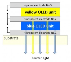
Figure 3: 2-unit/2-colour tunable OLED stack
To harvest yellow light emission as much as possible, the lower two electrodes have to show as high transmittance in the visible range as possible. The upper electrode is ususally realized by an opaque metal layer showing high reflectance.
Due to the three electrodes each single unit can be controlled separately. Thereby, monochrome blue light (x; y = 0,14; 0,12), monochrome yellow emission light (x; y = 0,46; 0,44) as well as different mixed emission spectra can be realized, as shown in figure 4.
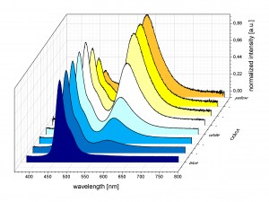
Figure 4: Emission spectra of the 2-unit/2-colour tunable OLED module at different dimming stages of each colouur unit realising emission colours between blue and yellow
The colour mixing of both fundamental emission colours (blue and yellow) is
achieved by dimming each independent unit. Here the brightness of each OLED unit is controlled by using pulse width modulation (PWM) because this method can be implemented with lower effort compared to amplitude modulation. The middle electrode thereby acts as a common cathode, but the two OLEDs can be driven independently
.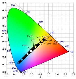
Figure 5: CIExy colour coordinate diagram with accessible colour mixtures at different dimming stages of the 2-unit colour tunable OLED module
3-colour tunable module
By using three basic emitters, the possible accessible colour gamut can be expanded to an triangle as depicted in figure 6. Here, three OLED units with the emitters red (x; y = 0,60; 0,40), green (x; y = 0,27; 0,66) and blue (x; y = 0,13; 0,16) are used. Thereby, each mixed colour on the connecting line between the fundamental colour points within the CIExy coordinate diagram are shown (figure 5), covering a correlated colour temperature region between 3000 K and 10000 K.
Thereby, a large number of different mixing shades can be realised. To control the three monochrome OLED units of the 3-unit stack shown in figure 7, an additional isolation layer between unit 2 and unit 3 is inserted.
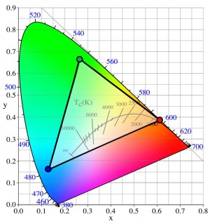
Figure 6: CIExy colour coordinate diagram with accessible colour area of the 3-unit/3-colour tunable OLED module
OLED outlook
There are multiple possibilities for the application of colour tunable OLED modules.
The main application area of course is lighting. This reaches from lighting solutions for residential areas, business areas and exhibition areas to intelligent office lighting. For example, matching the luminous perceived-colour interiors with the actual daytime may establish pleasant working atmospheres. Users also can design their individual illumination, such as choosing more cold white light in the morning to support working activities or warm white light in the evening for their relaxing leisure time.
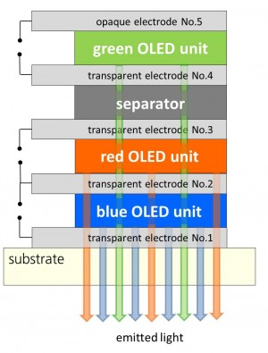
Figure 7: 3-unit/3-colour tunable OLED stack based on red, green and blue emitters
Due to the considerable effect of light on the human body and sense, colour tunable light sources may also be used as therapeutic application in medicine and healthcare. Light used as therapy against indications of stress, depression or jet-lag as well as to enhance memory and concentration individually customized for each person is possible. Fascinating applications in transportation including aviation, train and automobiles may also be found for these flat colour tunable light sources.
Written by Patricia Freitag, Tae-Hyun Gil, Jan Hesse, Dirk Schlebusch who are with the Fraunhofer Research Insitution for Organics, Materials and Electronic Devices COMEDD