


The global market for contact lenses is growing at more than 5% a year and is forecast to reach nearly $18 billion by 2025. Key drivers include more myopia among young people as well as a growing geriatric population has an increasing need for corrective lenses, especially with a multifocal design. Rising demand creates new challenges for manufacturers who must keep pace while maintaining strict product standards and quality assurances.
Contact lenses date all the way back to 1887, when they were made from blown glass. In 1948 the first plastic lenses were developed, and then soft contacts were introduced by Bausch + Lomb in 1971 and were made of a polymer based on the monomer hydroxyethyl methacrylate (HEMA). Called a hydrogel, they absorb water and were more comfortable than the old-style rigid lenses. Fast forward to 1999 and manufacturers began using silicone hydrogel, which have an even higher water content.
Quality control: measuring radius of curvature
Just as manufacturers have continually improved materials and design, they have also looked for new ways to ensure quality control. One critical aspect of each lens is the radius of curvature (RoC) of the surface. This can be determined via the mold or tool used in the lens’s production. As the main factor the RoC determines the diopter power of the lenses as well as its cylindrical power if toric lenses (with two main radii perpendicular to each other) are used to correct astigmatism in the eye. Additionally the mold’s surface deviation is inspected as it shows responsible for the correct imaging quality of the lens.
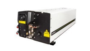
Many leading contact lens manufacturers are using a phase shifting interferometer from Trioptics for these measurements. The µPhase 3 system is capable of inspecting molds for both glass and plastic lenses as well as tools for injection molding, providing automatic measurements of all the values with very high accuracy. Prior to using an automated system, contact lens manufacturers had to make the measurements manually using an interferometer and a micrometer gauge. The drawbacks were the long measurement time, lower accuracy and potential for operator error.
Setup
The new equipment allows for semi-automatic radius measurements of spheric and toric samples with radius of curvature smaller than 200mm. It performs all the steps automatically: alignment of the sample, movement along the optical axis, interferometric measurement at each position, measurement of the travelled distance along the optical axis, calculation of radius of curvature, and then it moves to next sample.
The adjustment must be done manually using the sample adjustment unit, unless the operator adds a tray upgrade. A system equipped with a motorized x-y table enables the automated measurement of several molds in a batch. It is possible to use more than one tray at the same time, so while the measurement is taking place on one tray, another can be loaded with samples.
Once the molds positions in the tray are stored in the software, the operator can load the nominal sample values from a database and start the measurement. The system automatically moves to each mold or tool, measures its radius of curvature and surface deviation and shows or exports the results. Measurement time is between 20 and 90 seconds, including the mold positioning and the auto adjustment. A packed tray can be measured in just a few minutes, which is a doubling in efficiency compared to performing the same measurements manually.
Making the measurements
In making an absolute radius measurement, the sample radius is determined from two interferometric measurements of the sample: cat’s eye and confocal. The distance between the cat’s eye position and the confocal position together with the power correction in each position is the radius of curvature of the mold/tool. Toric samples (sphere + cylinder) are measured at four positions (cat’s eye, short confocal, long confocal and mid confocal) since they have two radii of curvature. The sample has to be aligned in reference to the interferometer. This moves between the focus positions of the sample along the optical axis. The measurement of the travelled distance has to be very accurate, as this is the primary measurement result. The interferometric measurement at the confocal position(s) give information about the surface deviation of the mold/tool.
According to Ralf Neubert, Trioptics application engineer, the potential challenges include positioning of the sample and automatic alignment of the sample. The actual radius of curvature of the sample should not differ more than 300 microns from the nominal one. Also sample positioning in xy has to be quite accurate (+-250 micron). “In reality this is no problem, since the parts are factory created and have a very small variation,” Neubert noted.
Real-world use
One major contact lens manufacturer uses more than 10 of these systems to measure the molds that they use to produce their contact lenses. They have different molds for each contact lens type. For each kind of mold they use a different tray that is designed for the specific mold type. Previously when the measurements were done manually, speed and accuracy were dependent on the operator. Accuracy then could be about 5 microns.
The customer concluded, “Now these automated systems have achieved an accuracy of RoC measurement below 1 micron and one operator can set up and use more than one interferometer at the same time, which saves cost and increases efficiency.”
Written by Anne Fischer, Managing Editor, Novus Light Technologies Today