


Equipment and infrastructure for machine vision inspection applications are a big investment, and users need to maximize that investment by getting the most out of these systems. A major challenge facing operators of such systems is lagging data transfer speed. The speed of new CMOS sensors, in the hundreds of frames per second, can outstrip the 115 MB/second gigabit Ethernet speed offered by GigE Vision, leading to a bottleneck as data is transferred. Other camera interfaces can offer a higher throughput, but might lack the longer cable reach of GigE Vision or its low cost. To get the most out of a machine vision inspection system, operators can pursue techniques to improve efficiency of transferring data via Ethernet.
There are a number of techniques for optimizing data transfer speed to help alleviate the bottleneck. No single technique is perfect for all applications, and each one has its pros and cons.
Playing with the pixel format to increase transfer efficiency
For color camera use, one approach is to transfer raw Bayer pixels, rather than color pixels, to improve transfer speed. Doing so will deliver a three-time throughput gain. Another option for color cameras is to transfer YCbCr information, rather than a fully decoded RGB image. This technique reduces transfer data by subsampling the chrominance (Cb and Cr) and keeping full resolution on the luminance (Y).
Equivalently, in monochrome, it might be possible to improve transfer rates by using fewer bits per pixel: the so-called “packed” data. For example, instead of using unpacked 16-bits per pixel to transfer a true ten-bit of information and padding the remaining six bits, one can revert to a ten-bit packed pixel format where padding bits are removed. This approach provides a 38% throughput improvement. One could also consider using less bit per pixels (e.g., eight instead of ten bits), however, using fewer bits per pixel results in lower dynamic range, making this an ineffective technique for inspection applications that require viewing fine contrast. However, this technique generally allows a higher frame rate. There are almost always compromises involved in the pursuit of improved data transfer speed.
Binning, scaling and decimation
Other options available for optimization include binning, scaling and decimation. They are all part of the family of sub-sampling techniques. Binning combines two or more consecutive lines or columns into one by adding or averaging pixels. It is generally performed inside the sensor and can result in a higher frame rate. Scaling is zooming in or zooming out of an image, by filtering and then reducing the image size. Decimation is the same, but generally without the filtering operation. With these three techniques, there is less data to transfer, but some of the frequency content is lost. For some industrial inspection applications, this is not an issue, but for others, these approaches are not a good option because they interfere with an effective inspection.
Multi-ROI approach to capture useful data
One of the most interesting techniques available to improve transfer speed is the multiple regions of interest (multi-ROI) approach.

Multi-ROI is exciting because it doesn’t require the loss of useful data from the image. Multi-ROI is in the same family as generic cropping – changing the image size by removing some of the border. However, instead of just one cropping region, users of the multi-ROI technique crop multiple rectangular areas in the image, combine the cropped areas and collapse them down to a single, smaller rectangular image.
Maximizing transfer speed using existing infrastructure
By maintaining a rectangular ratio, data transfer speed is increased via the multi-ROI approach without investing in new infrastructure. Image acquisition software and infrastructure have been designed to manage rectangular images. The user must identify exclusion lines and exclusion columns of unneeded information, and collapse the remaining useful data into a single rectangular image. The result is a smaller image than the original, including all of the important regions of interest, but cutting out the areas that don’t require inspection. Image transfer speed is increased because the resulting image is smaller than the original, while still containing all the vital information needed for inspection. The parts of the image that are lost are not relevant to the inspection.
The user must set up a multi-ROI approach from the camera perspective, specifying the sections to be kept, and the lines and columns to be cut. However, the resulting image is completely transparent to existing acquisition software, which only sees a smaller, rectangular image. Therefore, this approach works with existing infrastructure, including third-party acquisition software.
Applications for the multi-ROI technique
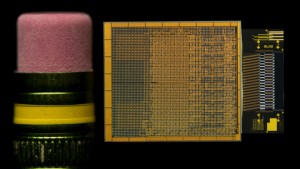
This technique is a great option for applications such as the inspection of solders on an electronic board.

It is ineffective for applications with images that can’t easily be cropped into a rectangle. For instance, an inspection of something round or ring-shaped, such as a tire, would not easily lend itself to the multi-ROI technique, since lines and columns of irrelevant data cannot be cropped out without cutting out relevant parts of the ring image.
Another advantage of the multi-ROI technique is that it can be combined with image acquisition cycling features to toggle acquisition configuration of each image in sequence. Using the multi-ROI technique would not prohibit the use of these features. For instances, let’s say you want to inspect a cycle of two groups of ROI on the same part. The first group of images is shot with regular white light, while the second group is viewed with a different light color – red or green. It would still be possible using the multi-ROI approach to view these different exposures in a cycle, even if the multi-ROI are not located at the same position for the white and red/green light flash.
Combining Multi-ROI with newer technologies
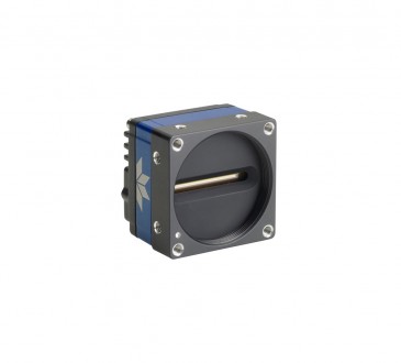
Multi-ROI can help increase transfer speed on existing systems. It can also be combined with newer technologies to further enhance throughput speed. For instance, Teledyne DALSA recently introduced new technology for its Linea GigE series, called TurboDrive, which more efficiently encodes pixel data into gigabit Ethernet packets, delivering dramatic increases in throughput, ranging from 20-150%.

The concept of Region of Interest (ROI)
New TurboDrive-enabled cameras can also employ the multi-ROI approach for appropriate inspection applications. Users deploying new, improved technology can couple it with the multi-ROI approach and reap even faster transfer speeds.
As outlined above, there are a number of approaches to reap faster data transfer speeds from your industrial inspection camera. Alone or in combination with new technologies, the multi-ROI approach to optimizing data transfer bandwidth is one of the most elegant options for many inspection applications. The ability to keep all useful data, discard unnecessary pixels and acquire the resulting image via any standard third-party acquisition software makes multi-ROI a very effective technique for getting more out of your industrial inspection camera.
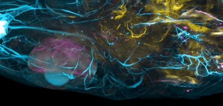
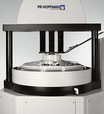
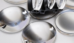
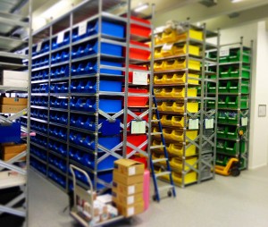
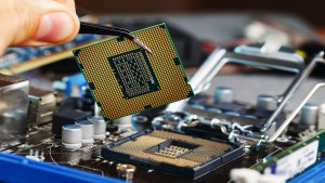
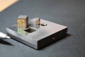
Photo at top: An advanced automated optical inspection (AOI) system for color filters. These types of systems are often used for things like flat panel display or solar glass inspection.
Written by Eric Carey, R&D Director for Area Scan Machine Vision & Frame Grabbers, Teledyne DALSA